11. HPM5300_RDC
11.1. Depend on SDK1.10.0
11.2. Overview
High performance motor control applications traditionally require a speed or position sensor for control loop feedback. The position feedback link has a critical impact on the performance of the system. Rotary transformers have become popular Angle sensors due to their advantages such as impact resistance, high temperature resistance, oil pollution resistance, high reliability, and long life.
At present, most of the existing rotary solutions in the market are discrete, with high BOM cost and large board area.
In order to simplify the design, HPM provides a functional rotary decode board integrating excitation op amp circuit, boost DC-DC chip, analog front end, rotary digital converter, rotary signal loss detection and multiple format data (position/speed) output interface.
11.3. RDC theory
rotary signal
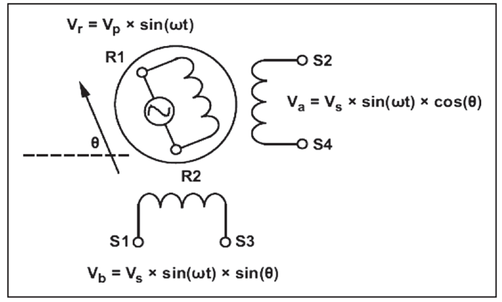
The rotor is composed of a rotor and a stator core. The middle rotor is composed of a laminated magnetic steel plate. The stator core is equipped with a single-phase excitation coil winding (R1-R2) and a two-phase output coil winding (S1-S3,S2-S4). When the excitation coil is excited by AC voltage, according to the transformer principle, there is a corresponding AC voltage on the output winding.
operating principle - integral demodulation
Integral demodulation can be divided into two processes: shaping and integration.
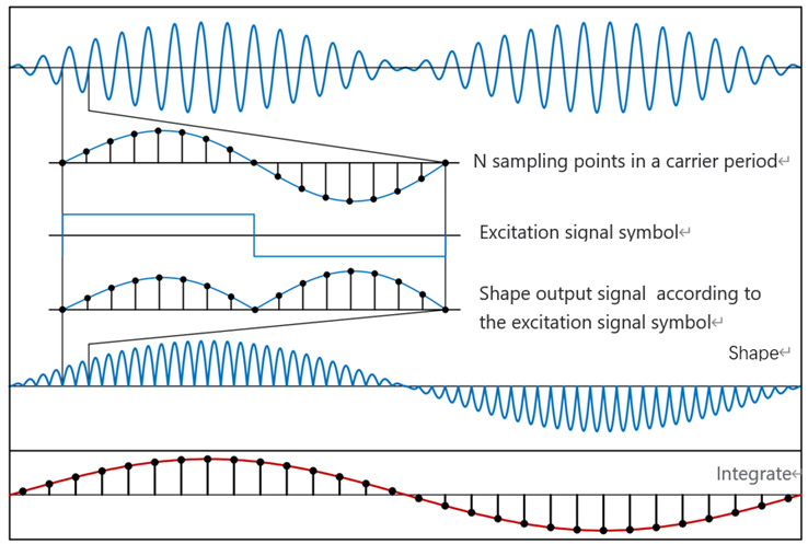
(1)shaping:
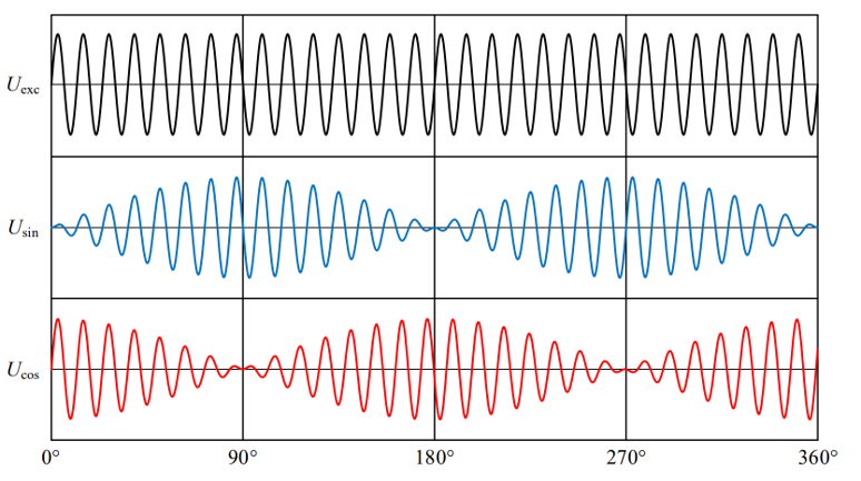
The sines and cosines of the output of the rotary transformer are multiplied by the sign function of the same frequency as the excitation signal
(2)integration:
The shaping results over the excitation period are integrated
After shaping and integration, the high frequency excitation signal is removed, and the demodulation signal containing the rotor information is obtained.
From the working principle, integral demodulation requires a high sampling rate, and the integration process has certain requirements on the computing rate of the processor.
position acquisition method
(1)arctan
Arctangent method is the most simple and direct method to solve the rotor Angle.
The arctangent function has a relatively large slope at the zero crossing, and a small interference in the output signal will cause a large Angle solution error. Therefore, arctangent is mostly used in situations where noise and accuracy are not required.
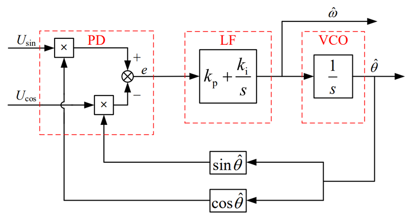
(2)Closed-loop Angle observer -PLL
It is mainly composed of phase discriminator (PD), loop filter (LF) composed of PI controller and voltage control oscillator (VCO) composed of integration.
The phase discriminator is used to generate a signal containing the phase deviation between the real Angle and the estimated Angle;
The loop filter uses PI controller to suppress noise interference, which determines the dynamic performance, tracking performance and stability of PLL. Its output is the rotor angular frequency.
A VCO is used to integrate angular frequencies to produce an estimated Angle value.
(3)TYPE_II loop tracking
TYPE_II loop tracking consists of three parts, integrator 1, filter compensator (one pole, one zero), integrator 2. The integrator is used to generate the Angle output from the velocity signal, and the filter is used to reduce the high frequency noise.
11.4. hardware solution
The overall scheme of RDC is shown in the figure below:
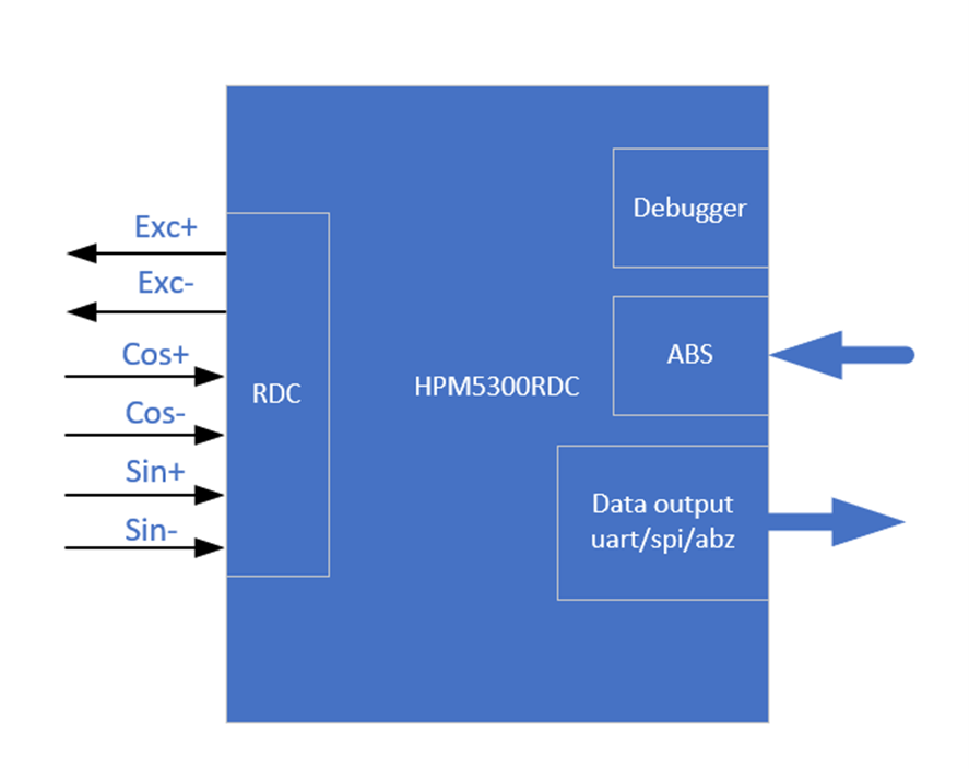
HPM5300RDC board has the following functions: two ADC, one uart, one spi, two DAC, QEO output, SEI master/slave, LED display, etc.
HPM5300RDCschematic diagram: 《HPM5300_RDC_REVB》
11.5. software solution
The software solution is mainly composed of the following parts:
pwm generates excitation signals, ADC samples, sei module obtains absolute encoder position information, three position/speed calculation methods (PLL_II/PLL/ arc-cut), incremental encoder simulation output (A_guad_B format), two data communication (uart/spi).
The sei module is used as the host to compare the obtained RDC Angle with the absolute encoder Angle for error analysis.
sei module can also be used as a slave. When used as a slave, there are bissc and TAMAGAWA output modes.
11.6. TEST
The test of this scheme is divided into three parts:
(1) Hardware test: pwm modulated sinusoidal differential signal (EXC_P/EXC_N), rotary sinusoidal winding signal (OSIN/OCOS) (2) Data output test: uart, spi,abz,bissc and TAMAGAWA (3) Error test: Angle error, speed fluctuation
11.6.1. test instrument
(1)Motor drive platform
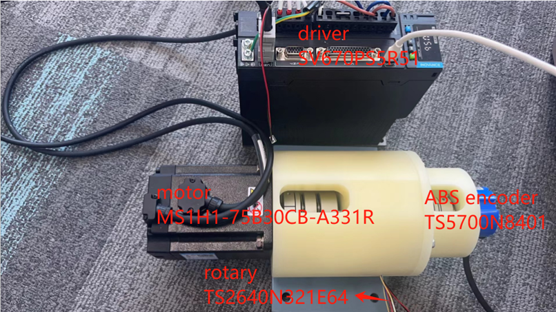
(2)hHPM5300RDC

(3)HPM5300EVK

11.6.2. testing environment
(1)HPM_RDC decoding software: hardware_rdc (2) Data communication software: pc_debug (3) ozone debugging tool (4) Huichuan driver debugging software: InoDriverShop (5) Jlink (6) RDC board pin description
function |
rotary plate location |
note |
|---|---|---|
EXC+ |
J4[5] |
rotary exc signal |
EXC- |
J4[6] |
rotary exc signal |
COS+ |
J4[1] |
rotary cos signal |
COS- |
J4[2] |
rotary cos signal |
SIN+ |
J4[3] |
rotary sin signal |
SIN- |
J4[4] |
rotary sin signal |
DAT+ |
J3[8] |
ABS signal |
DAT- |
J3[7] |
ABS signal |
PWR |
J3[5] |
24v,150mA |
GND |
J3[4] |
GND |
RX |
J3[1] |
uart 10M |
TX |
J3[6] |
uart 10M |
MOSI |
J3[6] |
spi |
CS |
J3[3] |
spi |
SCLK |
J3[2] |
spi |
MISO |
J3[1] |
spi |
QEO_A |
J3[3] |
ABZ |
QEO_B |
J3[2] |
ABZ |
QEO_Z |
J3[1] |
ABZ |
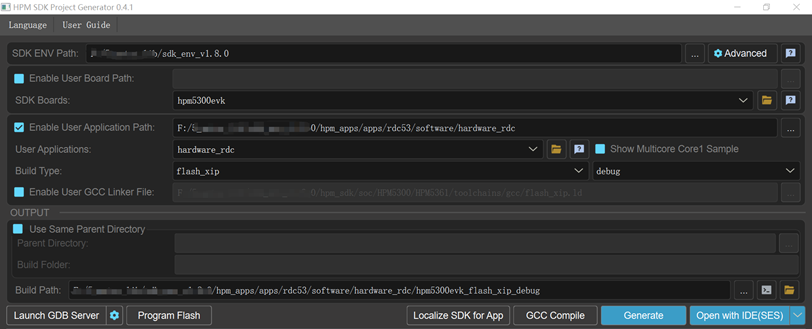
11.6.3. creat project
11.6.4. hardware test
(1)static state:
connect rotary signal to RDC
open the hardware_rdc project
Connect the debugger to the JTAG interface
Run the program
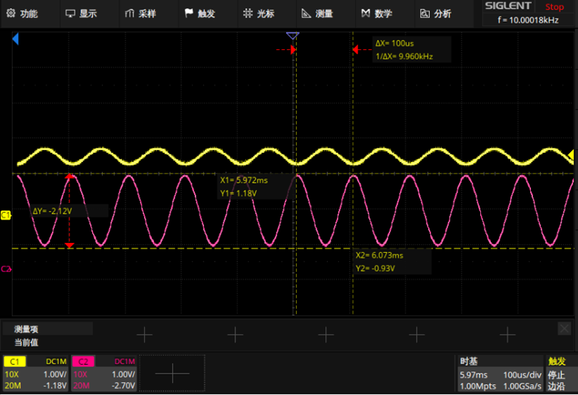
measure key signals by oscilloscope:
pwm modulated sinusoidal differential signal:EXC_P(yellow),EXC_N(pink)
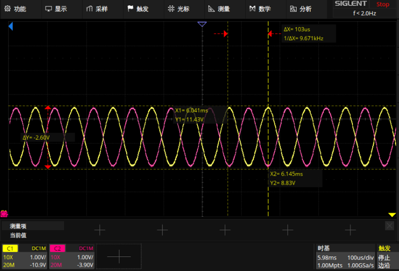
OSIN(yellow),OCOS(pink)
(2)In motion:
connect rotary signal to RDC
Create and open the hardware_rdc project
Connect the debugger to the JTAG interface
Run the program
move the motor manually
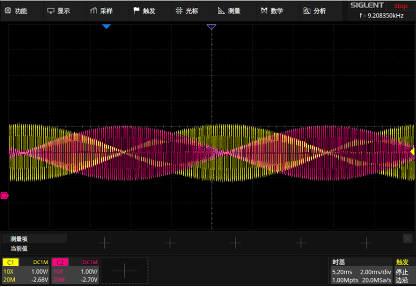
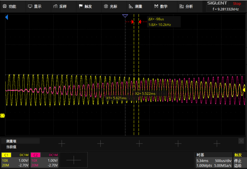
measure key signals by oscilloscope:
OSIN(yellow),OCOS(pink)
11.7. data output test
11.7.1. ABZ
11.7.1.1. test step
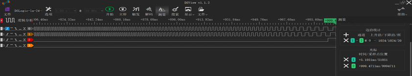
Wiring: Connect the ABZ signal to the logic analyzer
function |
rotary plate location |
|---|---|
QEO_A |
J3[3] |
QEO_B |
J3[2] |
QEO_Z |
J3[1] |
Create and open the hardware_rdc project.
Open the ABZ_OUTPUT macro definition in rdc program: #define ABZ_OUTPUT 1
Open the InoDriverShop debugging software and drive the motor to run one cycle at 100r/min
InoDriverShop debug refer to: SV670P系列伺服调试手册
11.7.1.2. result
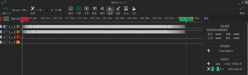
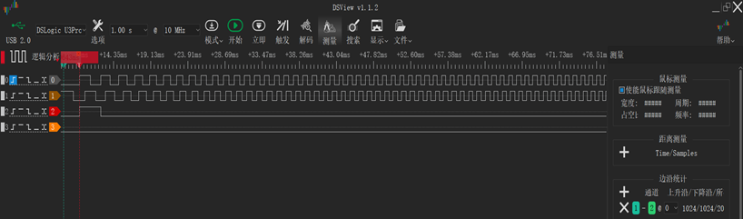
(1)The motor moves forward one cycle, phase A is 90 degrees ahead of phase B, output 1024 line pulse.
overall_fig:
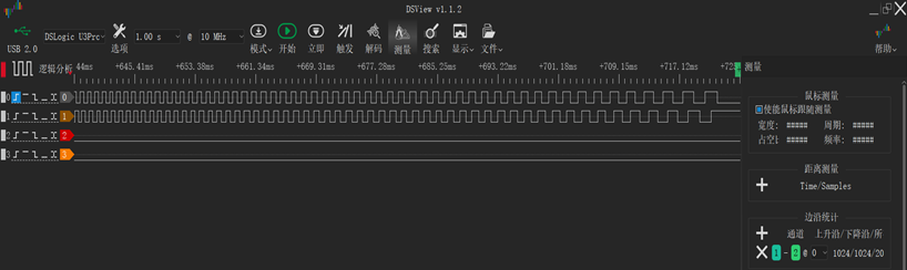
detail_acc:
detail_dec:
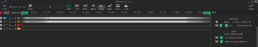
(2)The motor moves reverse one cycle, phase A is 90 degrees ahead of phase B, output 1024 line pulse.
overall_fig:
detail_acc:
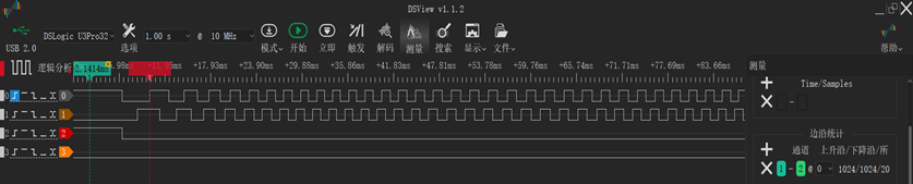
detail_dec:
11.7.2. uart
11.7.2.1. test step
Wiring, rotary plate and 5300evk plate common ground.
function |
rotary plate location |
5300evk location |
|---|---|---|
uart.rx |
J3[1] |
P1[8]/PB08 |
uart.tx |
J3[6] |
P1[10]/PB09 |
Open UART_DEBUG_CONTROL macro definition in rdc program: #define UART_DEBUG_CONTROL 1
Run the rdc program
Create and open pc_debug program, select serial port communication mode: #define UART_DEBUG 1
Running motor
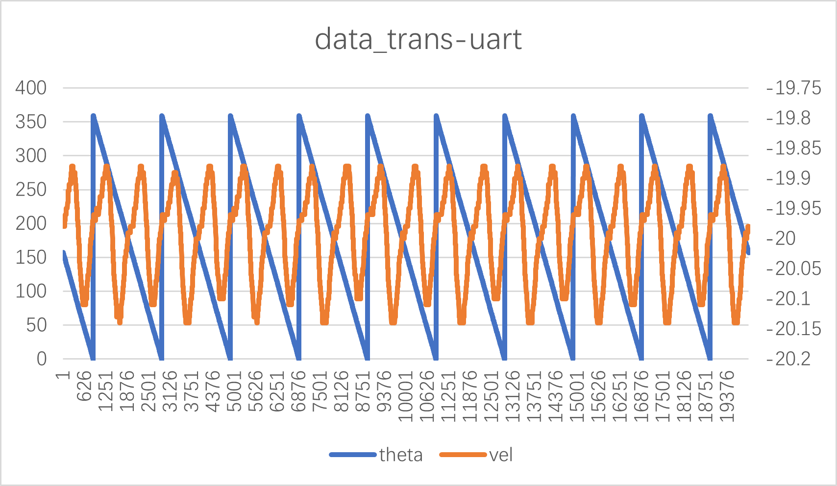
When the motor is running at constant speed, run pc_debug program
Take out the Angle and position information stored in the array theta_rdc,pll_vel, and process it with excel (divide the original data by 100)
11.7.2.2. test result
11.7.3. SPI
11.7.3.1. test step
Wiring, rotary plate and 5300evk plate common ground.
function |
rotary plate location |
5300evk location |
|---|---|---|
SPI.MOSI |
J3[6] |
P1[19]/PA29 |
SPI.CS |
J3[3] |
P1[24]/PA26 |
SPI.SCLK |
J3[2] |
P1[23]/PA27 |
SPI.MISO |
J3[1] |
P1[21]/PA28 |
Open SPI_DEBUG_CONTROL macro definition in rdc program: #define SPI_DEBUG_CONTROL 1
Run the rdc program
Open SPI_DEBUG macro definition in pc_debug program :#define SPI_DEBUG 1
Running motor
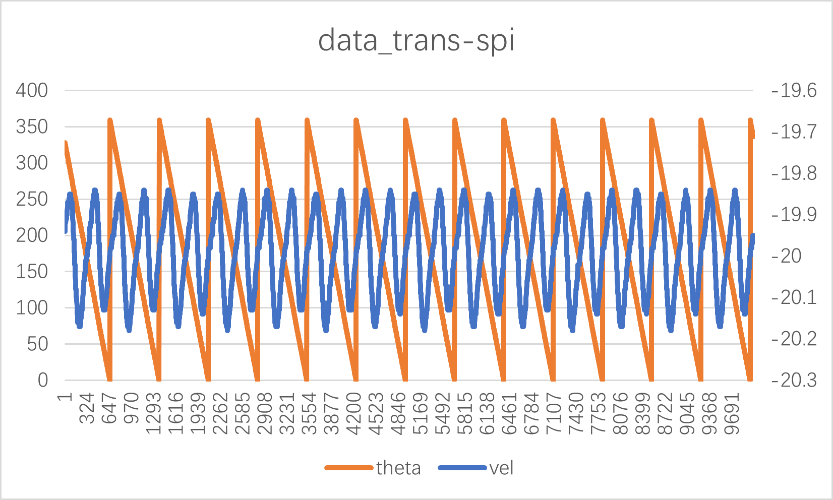
When the motor is running at constant speed, run pc_debug program
Take out the Angle and velocity information stored in the array rdc_theta,vel_pll, and process it with excel (divide the original data by 100)
11.7.3.2. test result
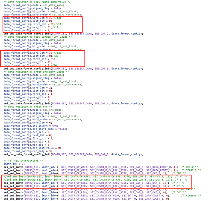
11.7.4. bissc clave mode
The SEI module is configured in slave mode and acts as an encoder to send out the rotary decoding position information. There are two ways:
Hardware tirg pos
rdc->qei->sei
0 corresponds to 0°, 0x100000000 corresponds to 360° (electrical Angle)
Software writes pos
11.7.4.1. Test procedure
When the data interface of HPM5300RDC board outputs bissc communication protocol, the 5 pins and 6 pins of U10 need to be cut off.
Master code paths: samples/drivers/sei/Master/bissc, and make the following changes:
Hardware triggered
a. Set the relevant macro definition in rdc_cfg.h
#define BISSC_SLAVE 1 #define BISSC_SLAVE_POS_HARDWARE_INJECT 1
b. Prepare a HPM5300evk board as the main machine.
Cross the Master’s SEI_CLK span needle to the Master side
Connect the Master’s SEI interface signal DATA_P/DATA_N with the Slave’s SEI interface signal DATA_P/DATA_N.
Connect the Master’s SEI interface signal CLKO_P/CLKO_N with the Slave’s SEI interface signal CLKI_P/CLKI_N.
Connect the Master’s GND to the Slave’s GND.
c. Download the master program to the HPM5300EVK board and the rdc program to the rotary board
d. View the log information output by each board through the serial terminal
Software writing
a. Set the relevant macro definition
#define BISSC_SLAVE 1 #define BISSC_SLAVE_POS_HARDWARE_INJECT 0
Step b.c.d is the same as (hardware injection)
11.7.4.2. Test results
(1) Hardware triggering
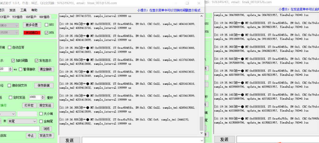
(2) Software injection

11.7.5. Tamagawa slave mode
The SEI module is configured in slave mode and acts as an encoder to send out the position information decoded by rotation. There are two ways:
Hardware tirg pos rdc->qei->sei 0 corresponds to 0°, 0x100000000 corresponds to 360° (electrical Angle)
Software writes pos
11.7.5.1. Test procedure
Hardware triggered
a. Set the relevant macro definition in rdc_cfg.h
#define TAMAGAWA_SLAVE_POS_HARDWARE_INJECT 1 #define TAMAGAWA_SLAVE 1
b. Prepare A USB-to-485 module to connect the SEI interface signal DATA_P/DATA_N with the A/B signal of USB-to-485
c. Download the program to the development board and run it.
d. Send Hex data through the serial debug assistant: ‘1A’ or ‘02’ or ‘8A’ or ‘92’, and the encoder simulated by the development board will respond. At the same time, you can view the log information output by the development board through the serial port terminal.
Software writing
a. Set the relevant macro definition
#define TAMAGAWA_SLAVE_POS_HARDWARE_INJECT 0 #define TAMAGAWA_SLAVE 1
b. Prepare A USB-to-485 module to connect the SEI interface signal DATA_P/DATA_N with the A/B signal of USB-to-485
c. Download the program to the development board and run it.
d. Send Hex data through the serial debug assistant: ‘1A’ or ‘02’ or ‘8A’ or ‘92’, and the encoder simulated by the development board will respond. At the same time, you can view the log information output by the development board through the serial port terminal
11.7.5.2. Test results
Hardware triggered
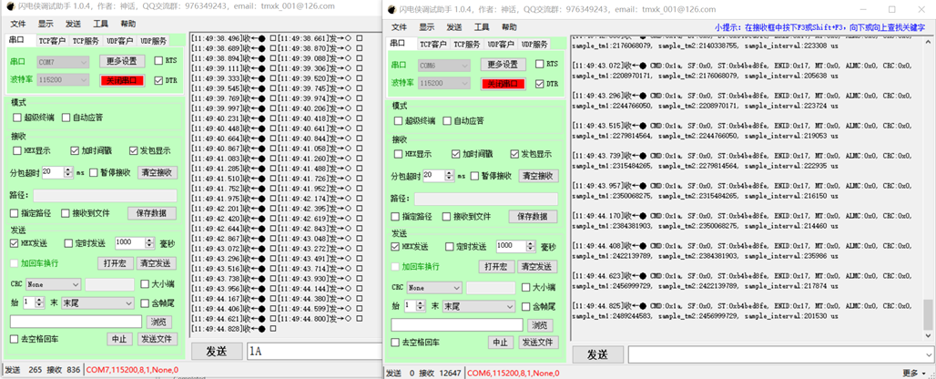
Software injection
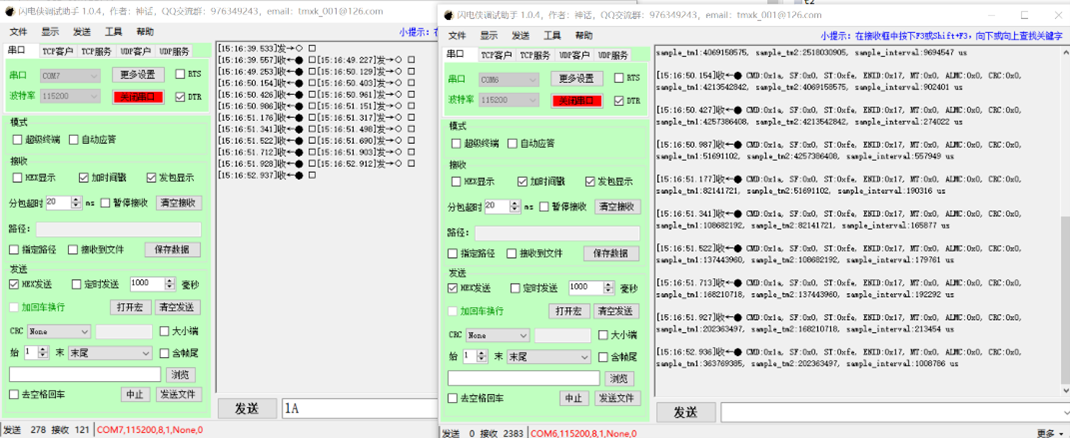
Note: Since the maximum baud rate of USB to 485 module used in the test is less than 2.5Mbps, the communication baud rate in the modified program is 115200, and it is changed back to 2.5Mbps in actual use.
11.8. error test
The Angle error test is based on the above motor driven platform, and the Angle difference is obtained by comparing the Angle of the rotary decoding board with the Angle of the absolute value encoder under steady speed.
There are three ways to calculate the Angle in the rotary decoding board: arctangent, pll,pll_ii; There are two corresponding speed calculation methods: the speed information is obtained based on the change of the fixed reading Angle, the speed information is directly output by the pll module ,and the speed information is directly output by the pll_ii module.
The speed fluctuation test is also based on the motor driven platform mentioned above, and the given speed at steady speed is compared with the sampling speed.
11.8.1. Angle error
11.8.1.1. test step
Connect the rotary signal, absolute encoder signal and power supply to the rotary plate according to the pin instructions in the test environment
Add to cmalist.txt in hardware_rdc:
sdk_compile_definitions(-DCONFIG_NDEBUG_CONSOLE=1)
sdk_ses_opt_lib_io_type(RTT)
start_gui.exe regenerate and open the hardware_rdc program
Open SEGGER_RTT_DEBUG, ABS_encoder_23bit macro definition in rdc program
#define SEGGER_RTT_DEBUG 1
#define ABS_encoder_23bit 1
open SEGGER_RTT_printf(0, “%d,%d,%d,%d,%d\r\n”,rdc_error,pll_error,pll_ii_error,pll_vel,pll_ii_vel);
build rdc program
Select debug with ozone and click the download button
Open Jlink-RTT-Logger v8.10d
Configure Target interface:JTAG,interface speed:9600, RTT control address:0x0008242C (find the address of _SEGGER_RTT in the demo.map file),RTT channel:0
Run the rdc program
Run the motor at 10, 20, 30, 40, 50r/s, respectively
Stop running the rdc program after collecting the location information for a period of time
Find the RTTLogger_Channel_Terminal.log file in C:\Users\XJXXX\AppData\Roaming\SEGGER
open data by excel, there are four columns of data collected, namely rdc_sei_theta_error,pll_sei_theta_error,pll_ii_sei_theta_error,pll_vel,pll_ii_vel
Data analysis: The Angle is periodic data of 0-360, and there is hysteresis in the Angle calculation. After calculating the error with the following formula, the points in the interval of (-300,300) are selected, and the points in the constant speed section can be taken.
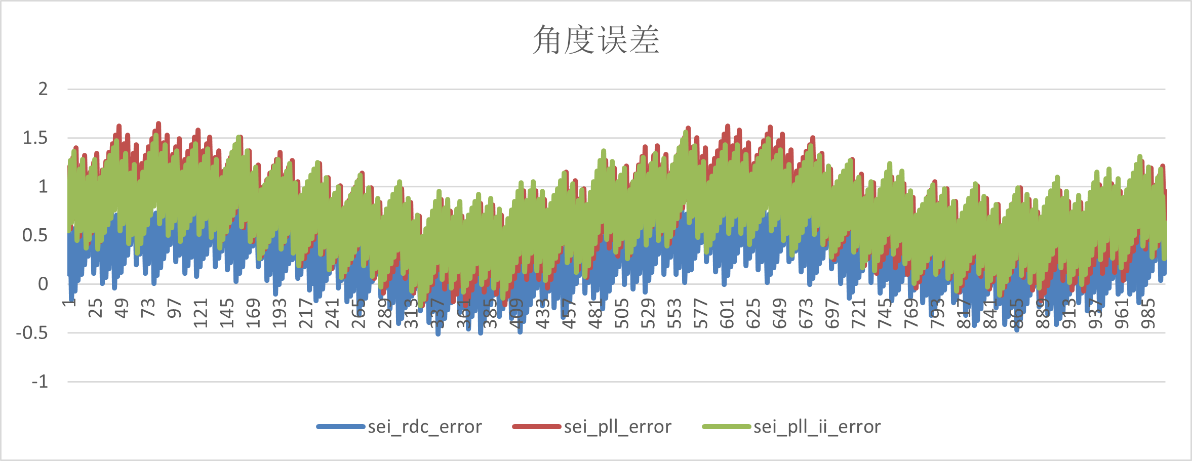
11.8.1.2. result
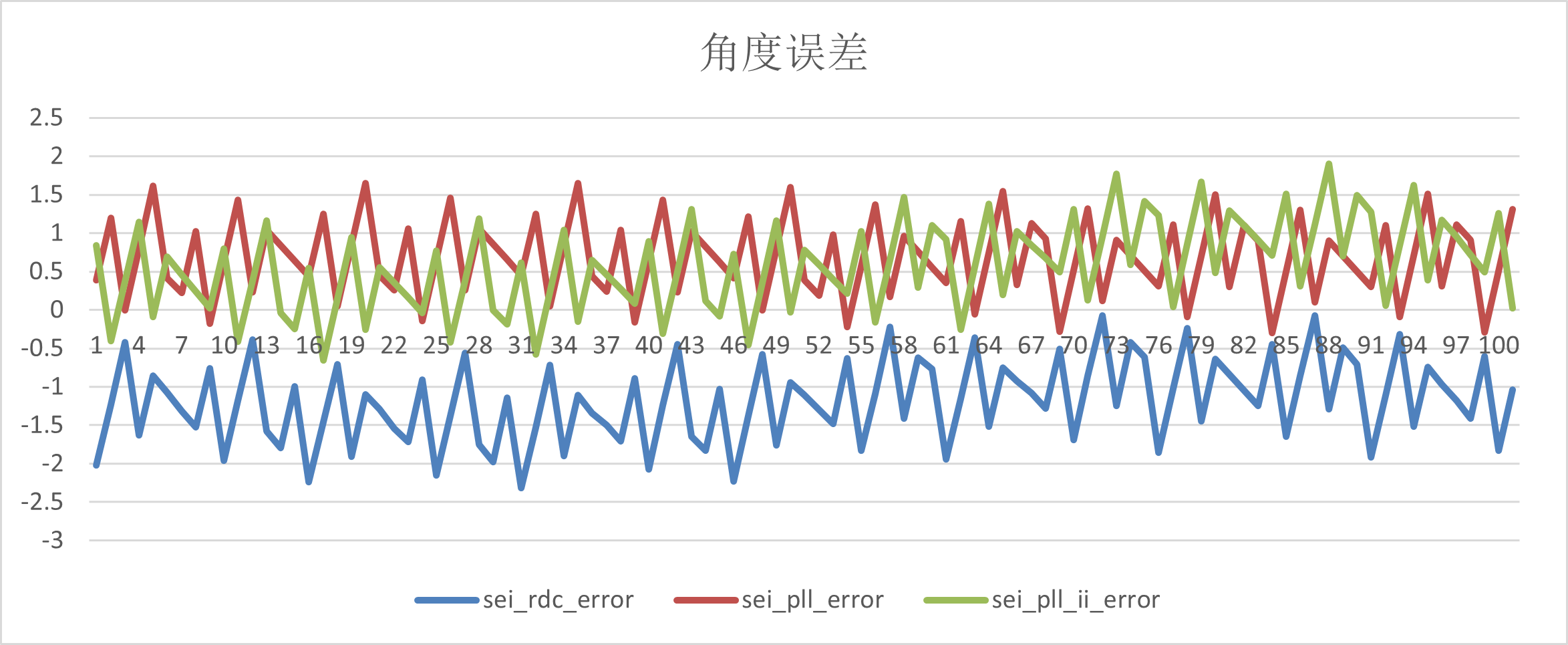
Angle error
vel_ref r/s |
sei_rdc_error |
sei_pll_error |
sei_pll_ii_error |
|---|---|---|---|
-10 |
(-0.51,1.13) |
(-0.2,1.57) |
(-0.04,1.45) |
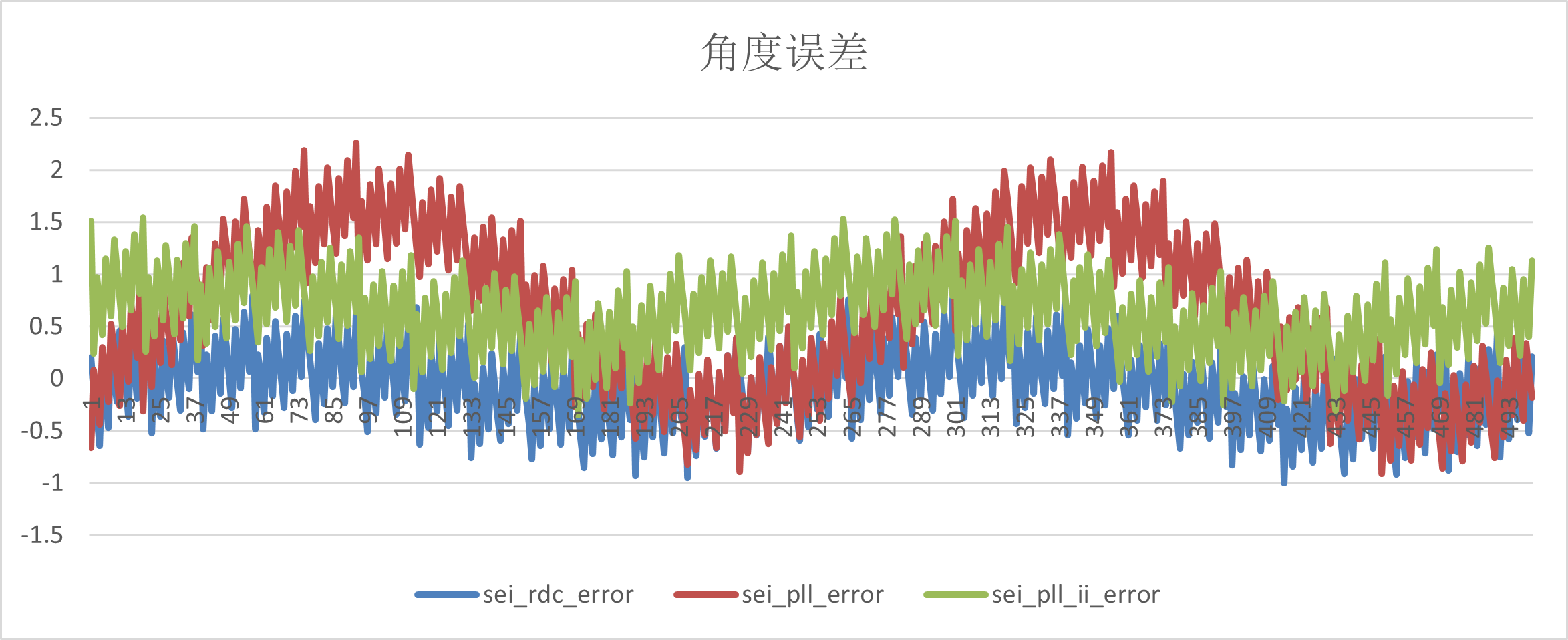
-20 |
(-1,0.92) |
(-0.91,2.3) |
(-0.4,1.58) |
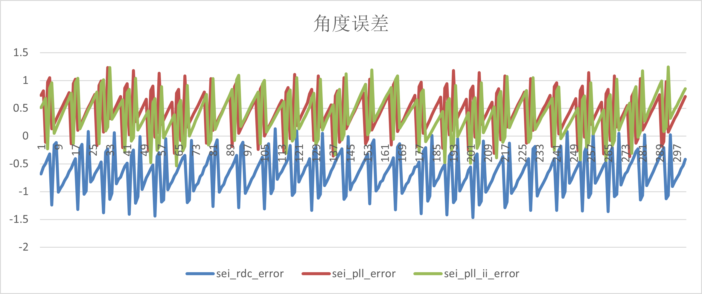
-30 |
(-1.5,0.2) |
(-0.44,1.26) |
(-0.54,1.36) |
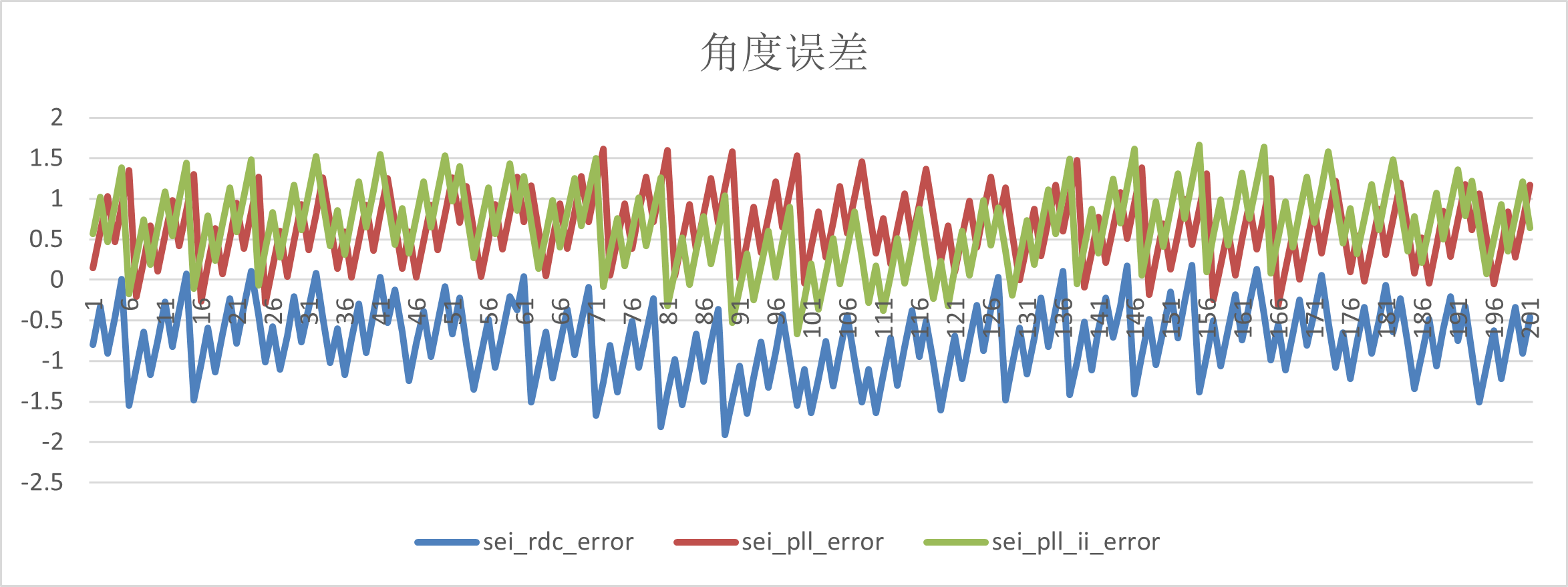
-40 |
(-1.89,0.26) |
(-0.3,1.59) |
(-0.7,1.93) |
-50 |
(-2.42,0) |
(0.047,1.136) |
(-0.79,1.86) |
(1)-10r/s
(2)-20r/s
(3)-30r/s
(4)-40r/s
(5)-50r/s
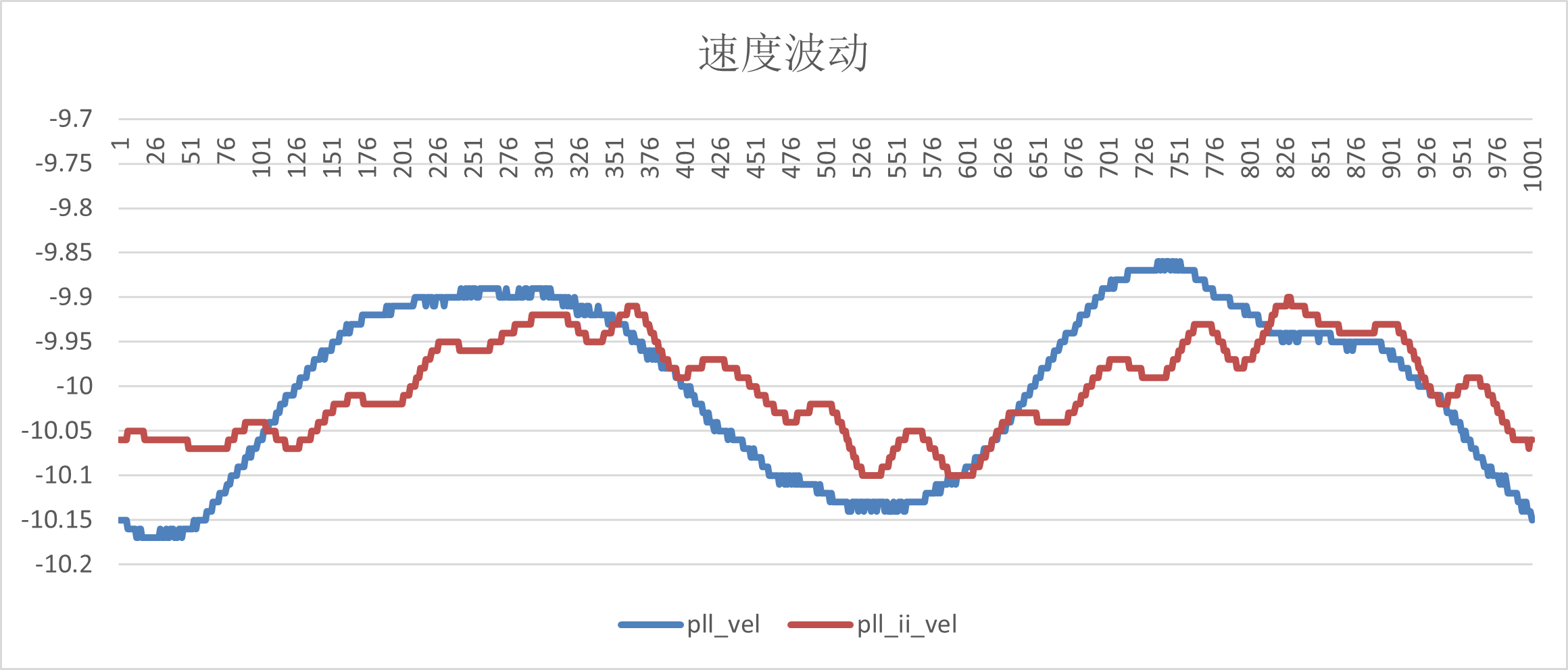
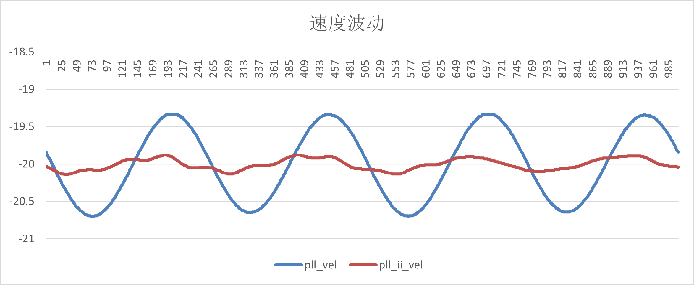
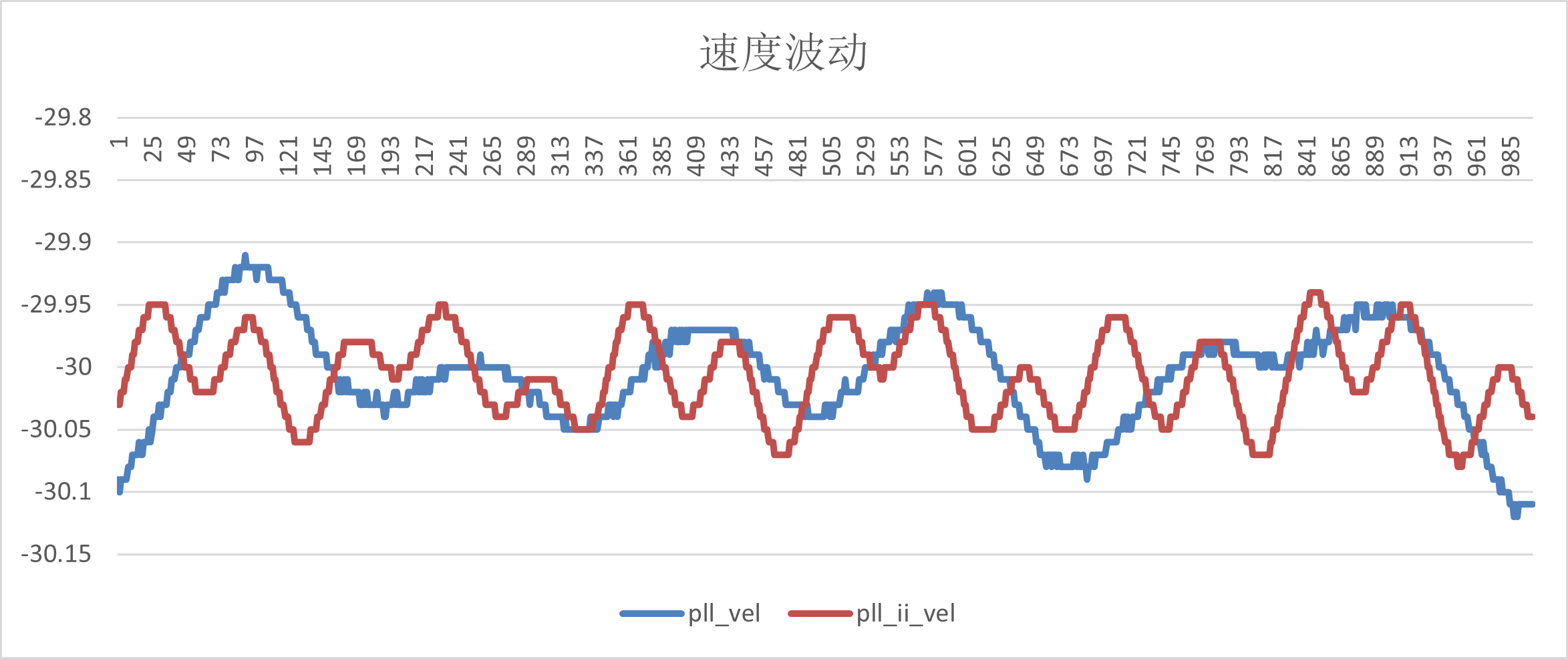
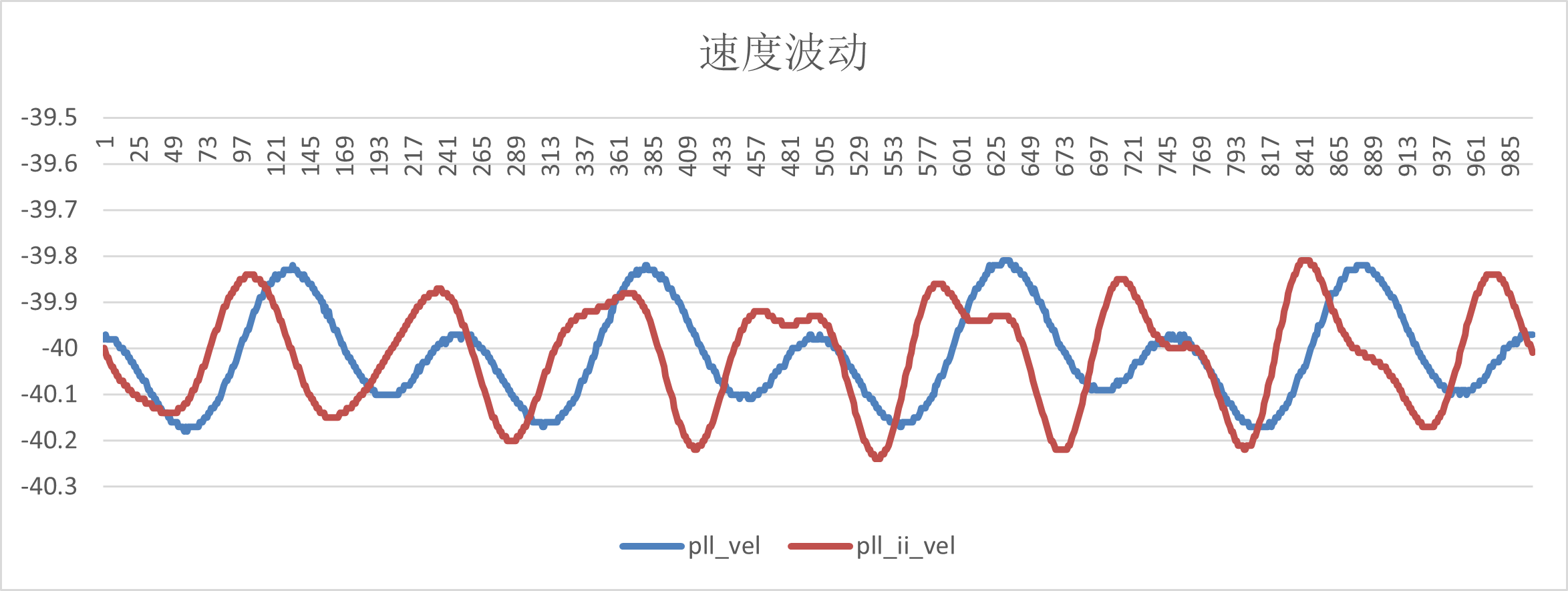
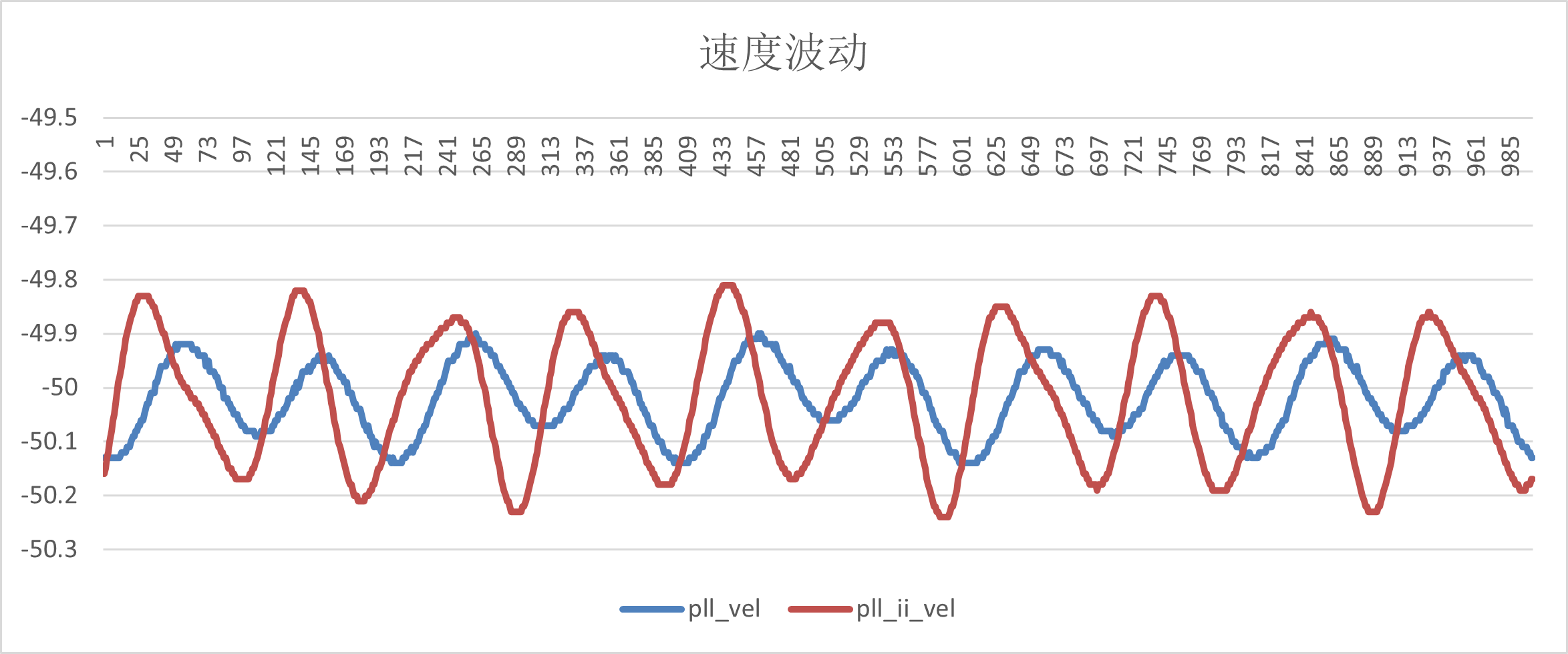
Velocity fluctuation
vel_ref r/s |
pll_vel |
pll_ii_vel |
|---|---|---|
-10 |
(-9.86,-10.17) |
(-9.93,-10.11) |
-20 |
(-19.5,-20.7) |
(-19.85,-20.14) |
-30 |
(-29.9,-30.13) |
(-29.9,-30.11) |
-40 |
(-39.82,-40.2) |
(-39.83,-40.22) |
-50 |
(-49.9,-50.14) |
(-49.8,-50.22) |
(1)-10r/s
(2)-20r/s
(3)-30r/s
(4)-40r/s
(5)-50r/s
11.8.2. Test Summary
(1) EXC_P, EXC_N, OSIN and OCOS signals of static and dynamic tests meet the requirements;
(2)UART and SPI communication function is normal, and the read data is consistent with the set motor parameters;
(3)bissc from the mode, Tamagawa from the mode correct output Angle, location information;
(4) The A/B/Z phase output of QEO is normal, and the output waveform is consistent with the set motor parameters;
(5) The Angle error data were tested at 10r/s, 20r/s, 30r/s, 40r/s and 50r/s speeds respectively. Compared with the absolute encoder, the arctangent Angle error of RDC was ±2.5 electrical Angle, the Angle error of PLL observer was ±2.3 electrical Angle, and the Angle error of PLL_II was ±2 electrical Angle. All meet the spec of ±3.
(6) The speed fluctuation range of PLL and PLL_II is ±0.3r/s at medium, low and high speeds.