22. HPM6750 Combo Board Functionality and Performance Test
22.1. Depends on SDK1.11.0
22.2. Overview
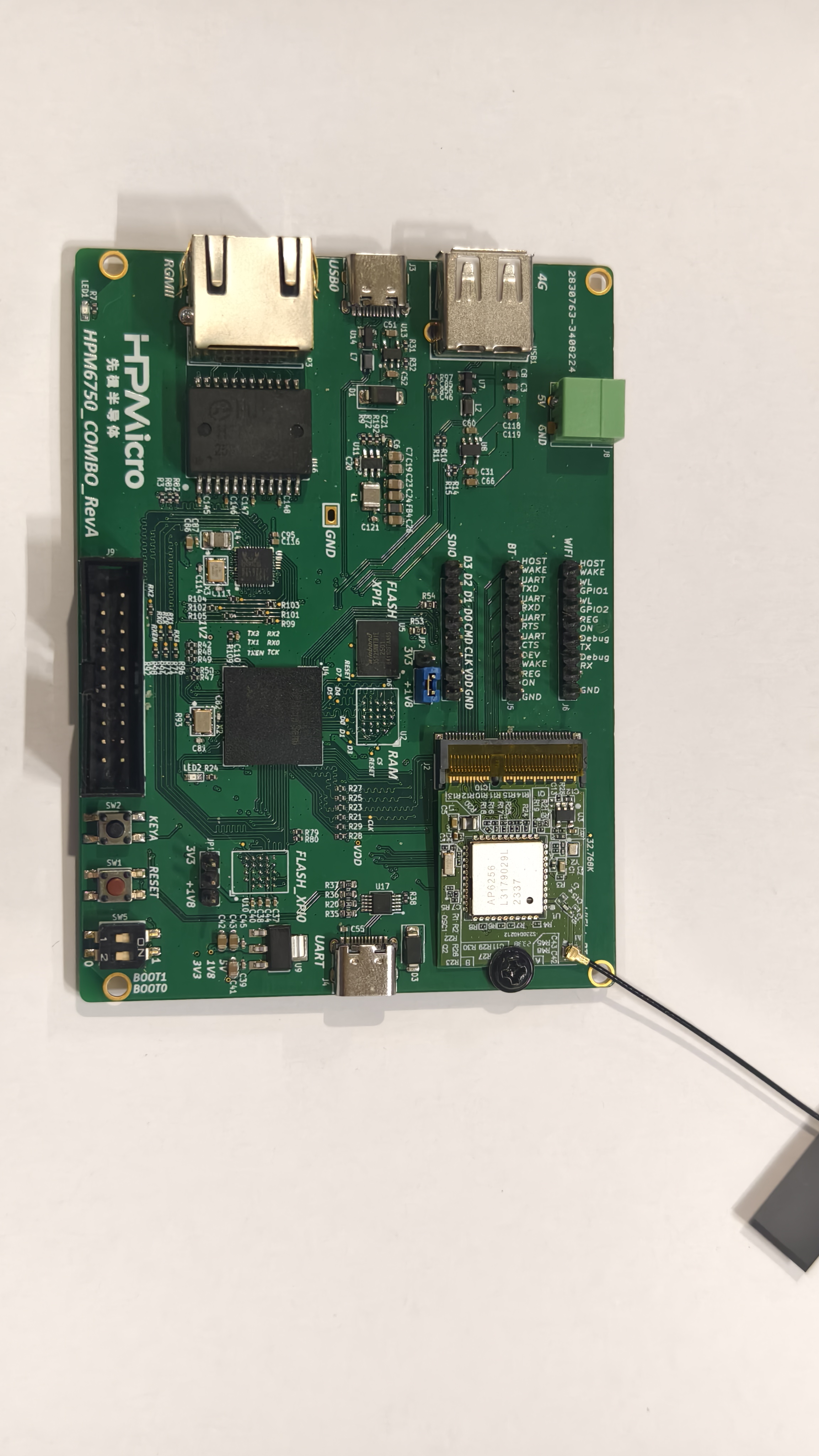
This section mainly introduces the demo usage of the HPM6750 Combo development board. The HPM6750 Combo development board is a development platform based on the HPM6754 MCU, with a built-in 4M flash and onboard USB device, USB host, SDIO WIFI, RGMII, XPI0 8-line, XPI1 8-line and other interfaces, making it convenient for users to test the functions and performance of HPMicro’s high-performance peripherals.
Key Features:
Onboard XPI0/XPI1 8-line interface, supports booting code from this FLASH, providing higher data transfer rates to improve system performance
Dual USB interfaces with built-in high-speed PHY, supporting both USB device and USB host functions to meet different application needs
Onboard SDIO WIFI interface with AP6256 module for high-speed wireless communication, up to 90Mbps
Ethernet peripheral based on RGMII interface for high-speed network communication, up to 900Mbps
The demos based on the HPM6750 Combo development board are as follows:
Project Name |
Description |
Default Code Execution Location |
|---|---|---|
hello_world_xpi0_internal |
A helloworld demo based on built-in FLASH, use hpm_sdk/examples/helloworld directly |
Built-in Flash |
boot_to_xpi1_octal_flash |
Bootloader required for running code from XPI1 |
Built-in Flash |
hello_world_xpi1 |
A helloworld demo based on external XPI1 |
External XPI1 Octal Flash |
cherryusb_device |
A device demo based on cherryusb, use hpm_sdk/examples/cherryusb/device directly |
Built-in Flash |
cherryusb_host |
A host demo based on cherryusb, use hpm_sdk/examples/cherryusb/host and apply patch (see below) |
Built-in Flash |
mhd_wifi_demo |
SDIO WIFI demo, use hpm_sdk/examples/lwip/mhd_wifi_demo and apply patch (see below) |
Built-in Flash |
rgmii_lwip |
LWIP demo based on RGMII interface, use hpm_sdk/examples/lwip and apply patch (see below) |
Built-in Flash |
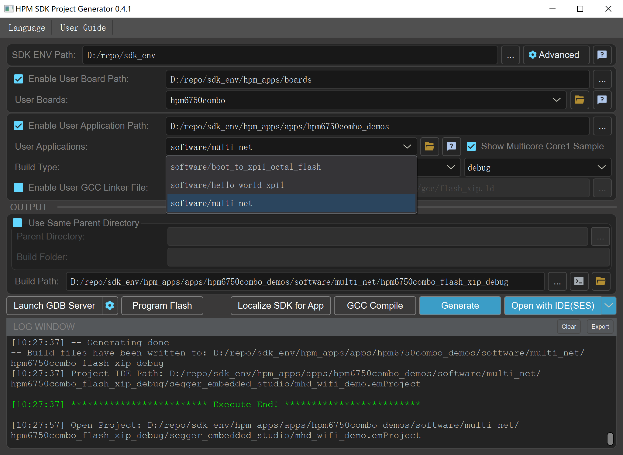
multi_net |
USB 4G + SDIO WIFI + RGMII three-in-one LWIP demo |
Built-in Flash |
When using the above examples, you need to select hpm6750combo as the BOARD in SDK_ENV.
22.3. hello_world_xpi0_internal
This demo demonstrates a helloworld demo based on built-in FLASH. Use hpm_sdk/examples/helloworld directly without any additional modifications.
22.4. boot_to_xpi1_octal_flash
This demo demonstrates the bootloader required for running code from XPI1. The HPM6750 Combo development board has an onboard FLASH based on the XPI1 8-line interface. Users can flash code to this FLASH and boot the code from it via the bootloader, where the internal FLASH is used only as the bootloader. Compared to traditional 4-line Flash, 8-line Flash can provide higher data transfer rates at the same clock frequency, thereby improving system performance.
boot_to_xpi1_octal_flash can be flashed via a debugger or the HPM MFG Tool. The flashing method is the same as for SDK demos and will not be repeated here.
The XPI1 configuration procedure is as follows:
Enable XPI1 clock
Configure the XPI1 peripheral: enable 8-line mode, set frequency to 133MHz, set IO voltage to 1.8V, select 2nd group for Pin group
    config_option.header.U = 0xfcf90002;
#if 1
    config_option.option0.freq_opt = 7;
    config_option.option0.probe_type = xpi_nor_xccela_ddr;
    config_option.option0.cmd_pads_after_init = XPI_8PADS;
    config_option.option0.cmd_pads_after_por = XPI_1PAD;
#else
    config_option.option0.freq_opt = 1;
#endif
    config_option.option1.io_voltage = 1;
    config_option.option1.pin_group_sel = 1;

    hpm_stat_t status = rom_xpi_nor_auto_config(HPM_XPI1, &config_block, &config_option);
    if (status != status_success) {
        config_option.option0.cmd_pads_after_por = XPI_8PADS;
        status = rom_xpi_nor_auto_config(HPM_XPI1, &config_block, &config_option);
        if (status != status_success) {
            printf("FLASH initialization failed, fall back to ISP mode...\n");
            fallback_to_isp();
        }
    }
    HPM_IOC->PAD[IOC_PAD_PC20].PAD_CTL = IOC_PAD_PAD_CTL_DS_SET(7) | IOC_PAD_PAD_CTL_MS_SET(1);
Read the boot header starting at firmware offset 0x1000, parse the entry point and load address from the boot header, and jump to the entry point to execute the code
    memcpy(image_buf, (void*)0x90001000, sizeof(image_buf));
    const boot_image_hdr_t *boot_hdr = (boot_image_hdr_t *)image_buf;
    handle_boot_image(boot_hdr);
22.5. hello_world_xpi1
This demo demonstrates a helloworld demo based on external XPI1. It must be used together with the boot_to_xpi1_octal_flash demo: first flash the bootloader to the built-in FLASH, then flash the helloworld demo to the external XPI1 Flash, and finally boot the helloworld demo from the external XPI1 Flash via the bootloader.
Note: Currently, flashing to XPI1 Flash can only be done using the HPM MFG Tool. Debuggers such as JLink cannot be used for flashing or debugging.
The steps to flash XPI1 Flash using HPM MFG Tool are as follows:
Compile hello_world_xpi1 to generate demo.bin
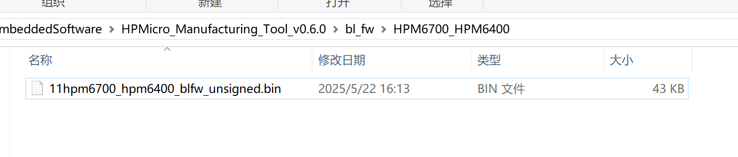
Delete or rename the file
bl_fw\HPM6700_HPM6400\hpm6700_hpm6400_blfw_unsigned.binin the HPM MFG Tool directory (e.g., rename it to11hpm6700_hpm6400_blfw_unsigned.bin), otherwise it cannot communicate with the bootrom
Pull the boot0 pin high on the board and power on. Note: Every flashing operation requires a full power-off and restart. Do not use the reset button to restart for flashing, because the XPI1 Flash running state is not controlled by reset.
Import the demo.bin file, check the custom Flash configuration option, select 2nd Group for Pin group, and select 1.8V for IO Voltage
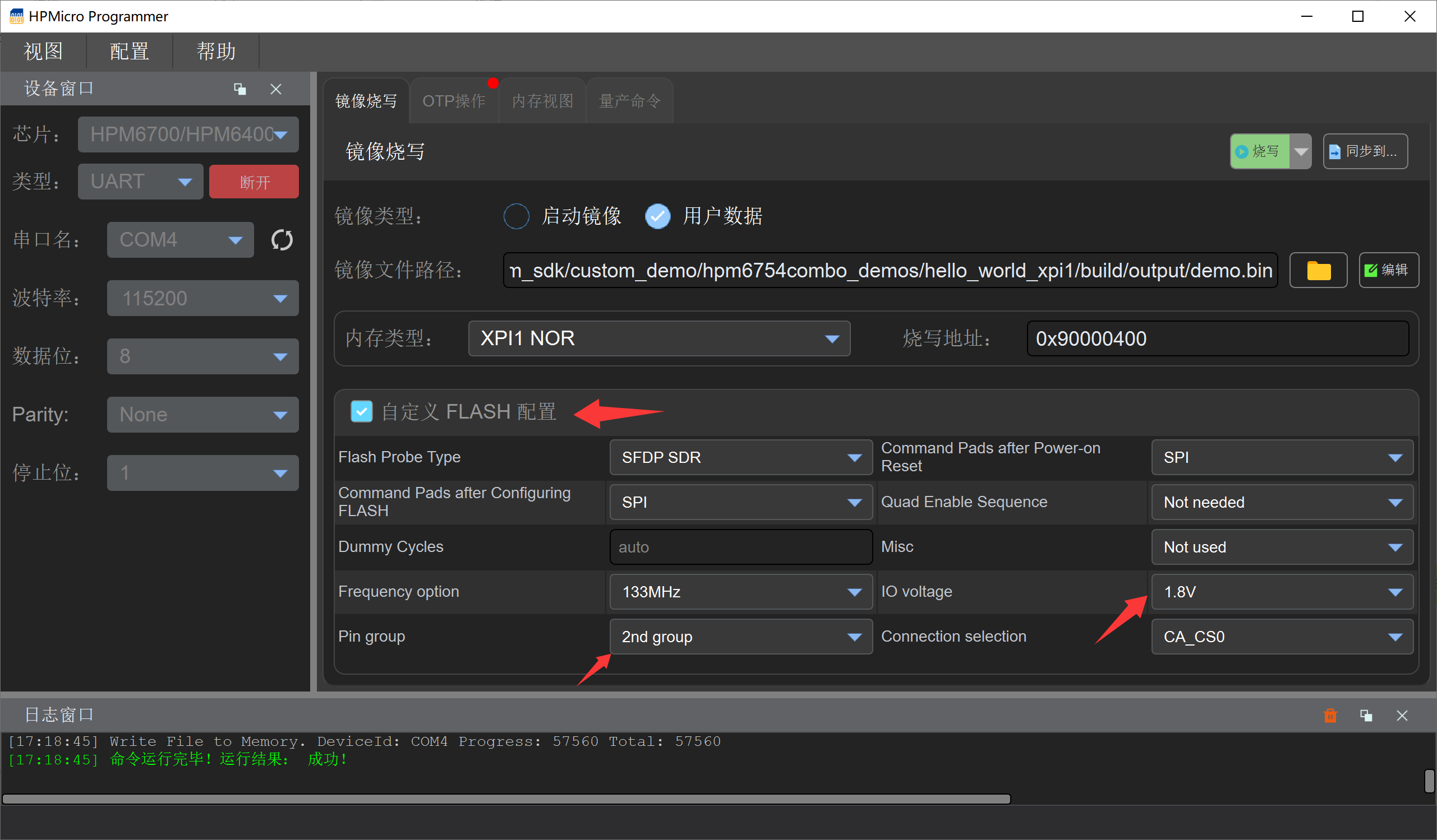
Click the flash button
22.6. cherryusb_device
This demo demonstrates a device demo based on cherryusb, using USB0 by default. Use hpm_sdk/examples/cherryusb/device directly without any additional modifications.
22.7. cherryusb_host
This demo demonstrates a host demo based on cherryusb, using USB1 by default. When using hpm_sdk/examples/cherryusb/host, the following modifications are required:
examples/cherryusb/config/usb_config.h
#ifndef CONFIG_HPM_USBH_BASE
#define CONFIG_HPM_USBH_BASE HPM_USB1_BASE
#endif
#ifndef CONFIG_HPM_USBH_IRQn
#define CONFIG_HPM_USBH_IRQn IRQn_USB1
#endif
If using USB0 as host, no modifications are needed.
22.8. mhd_wifi_demo
This demo demonstrates the use of SDIO WIFI. When using hpm_sdk/examples/lwip/mhd_wifi_demo, the following modifications are required:
samples/lwip/mhd_wifi_demo/CMakeLists.txt
if (${BOARD} STREQUAL "hpm6750combo")
    set(CUSTOM_GCC_LINKER_FILE ${CMAKE_CURRENT_SOURCE_DIR}/linker_file/HPM6700/gcc/mhd_wifi_flash_xip.ld)
    set(CUSTOM_SES_LINKER_FILE ${CMAKE_CURRENT_SOURCE_DIR}/linker_file/HPM6700/ses/mhd_wifi_flash_xip.icf)
elseif (${BOARD} STREQUAL "hpm6800evk")
    set(CUSTOM_GCC_LINKER_FILE ${CMAKE_CURRENT_SOURCE_DIR}/linker_file/HPM6800/gcc/mhd_wifi_flash_xip.ld)
    set(CUSTOM_SES_LINKER_FILE ${CMAKE_CURRENT_SOURCE_DIR}/linker_file/HPM6800/ses/mhd_wifi_flash_xip.icf)
else()
    message(FATAL_ERROR "Error: Unsupported board!")
endif ()

# Enable the external RAM initialization logic
#sdk_compile_definitions(-DINIT_EXT_RAM_FOR_DATA=1)
22.9. rgmii_lwip
This demo demonstrates the LWIP demo based on the RGMII interface. When using hpm_sdk/examples/lwip, you need to add the rtl8211f PHY driver. Follow the steps below (this step is not required if using hpm_sdk >= v1.12):
samples/lwip/common/single/common.c
Replace samples/lwip/common/single/common.c with multi_net/common/common.c, and remove enet_tx_control_config.cic = enet_cic_disable;, because the SDK uses hardware CRC verification by default.
Copy the rtl8211f folder to the example directory, e.g., copy it to the lwip_ping_freertos_socket directory
Modify the CMakeLists.txt file in the example directory, e.g., modify
lwip_ping_freertos_socket/CMakeLists.txt, and addadd_subdirectory(rtl8211f)to compile the rtl8211f driver
...
project(lwip_tcpclient_freertos_socket_example)
...
add_subdirectory(rtl8211f)
generate_ide_projects()
22.10. multi_net
This demo demonstrates the capability of simultaneously using USB 4G + SDIO WIFI + RGMII three network interfaces on the HPM6750 Combo development board. All three network interfaces are managed through the lwIP protocol stack, running independently without interfering with each other.
22.10.1. Functional Architecture
Network Interface |
Module / Peripheral |
Max Speed |
Description |
|---|---|---|---|
RGMII Wired Ethernet |
RTL8211F PHY |
~900 Mbps |
High-speed wired network, suitable for low-latency, high-bandwidth scenarios |
SDIO WIFI |
AP6256 Module |
~100 Mbps |
Wireless network, supports 2.4G/5G dual-band |
USB 4G |
Based on USB CDC-ECM/RNDIS, Quectel EC20 dial-free version recommended |
Depends on carrier |
Provides WAN access via 4G module, suitable for scenarios without wired network or WIFI |
22.10.2. Usage Instructions
Ensure the BOARD is selected as
hpm6750comboEnsure the SDIO WIFI module (AP6256) and 4G module are correctly inserted into their respective interfaces before use
The RGMII interface needs to be connected to an active network via an Ethernet cable
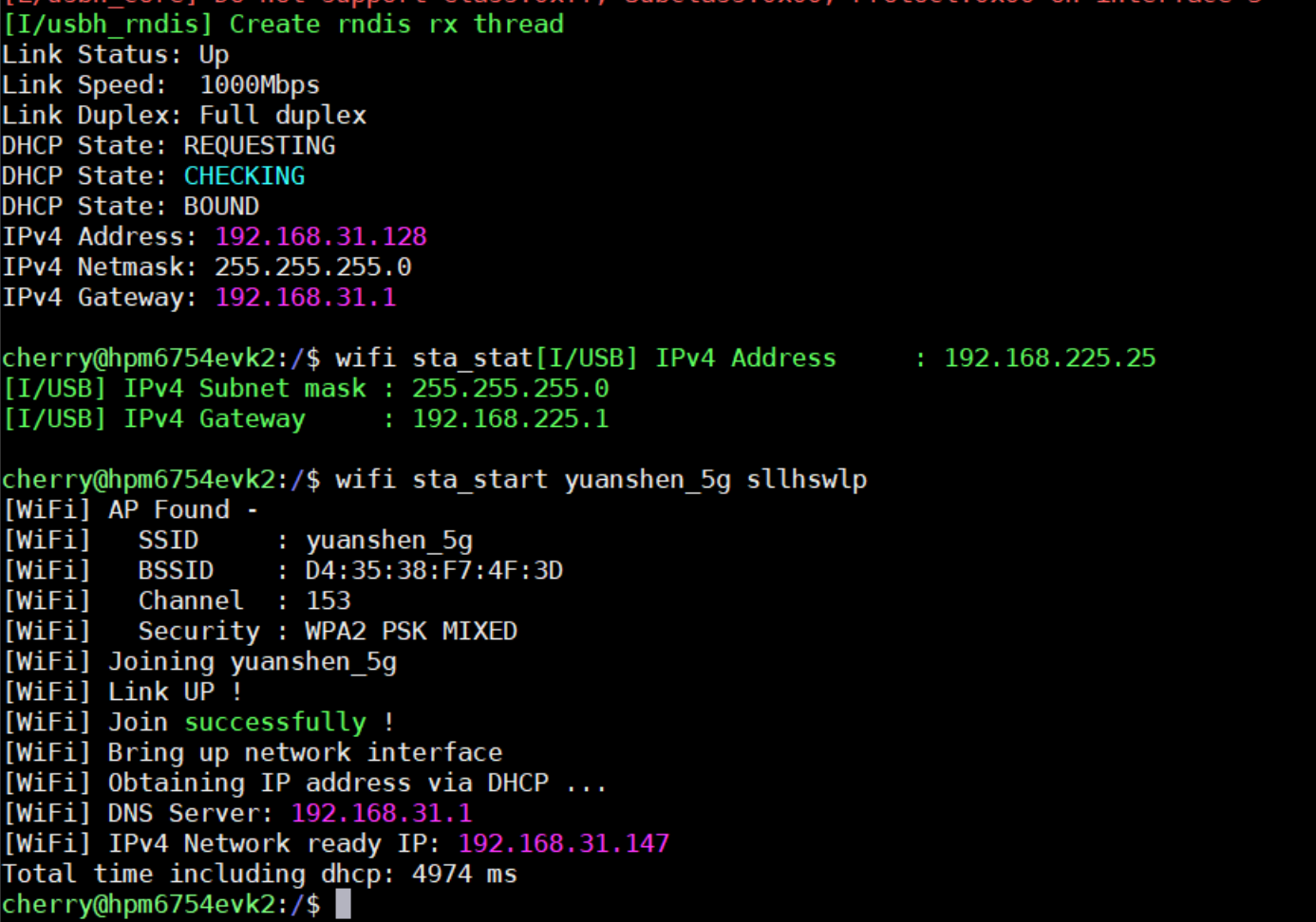
Default network interface names: RGMII en, SDIO WIFI w0, USB 4G EX
Use
wifi sta_start <SSID> <PASSWORD>to connect to WIFIAfter all interfaces are connected to the network, each interface will print its obtained IP address
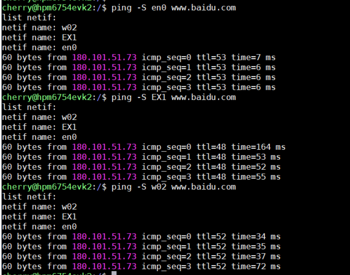
Use the ping command to test a specific network interface. Use the
-Soption to specify the interface. Note that the interface name passed should include interface name + netif index. For example, if the RGMII interface name isenand the netif index is0, pass en0, and so on.
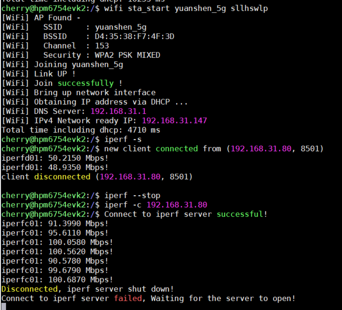
WIFI iperf TCP command test
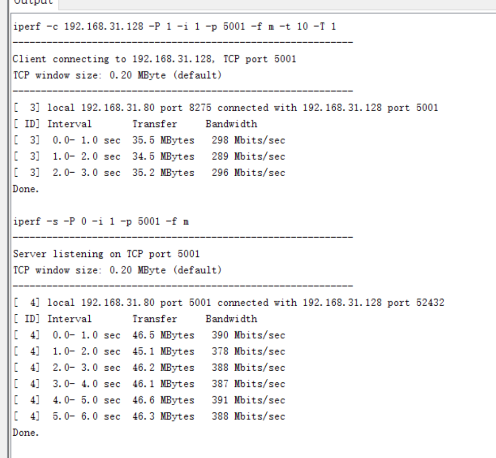
RGMII iperf TCP command test
22.10.3. Notes
The netif index is automatically assigned by netif_add calls. After connecting and disconnecting, the netif index of the same interface name may change. Therefore, during testing, use the interface name as actually printed to specify the correct interface name.
RGMII uses software CRC calculation, which reduces RGMII performance, because SDIO WIFI and USB 4G only support software CRC.
The values of ENET_TX_BUFF_COUNT and ENET_RX_BUFF_COUNT in RGMII affect its performance. Increasing them increases RAM usage. It is recommended to adjust these parameters based on actual requirements to improve RGMII performance.
The values of TCP_SND_BUF and TCP_WND affect TCP performance. Increasing them increases RAM usage. It is recommended to adjust these parameters based on actual requirements to improve TCP performance. If set too large while ENET_TX_BUFF_COUNT and ENET_RX_BUFF_COUNT in RGMII are small, TCP may send data too fast causing the RGMII transmit buffer to be insufficient, or receive too fast causing RGMII receive overflow, both of which would degrade performance.