23. HPM68 Series: Multi-Layer Dashboard Solution
23.1. Requires SDK 1.11.0
23.2. Overview
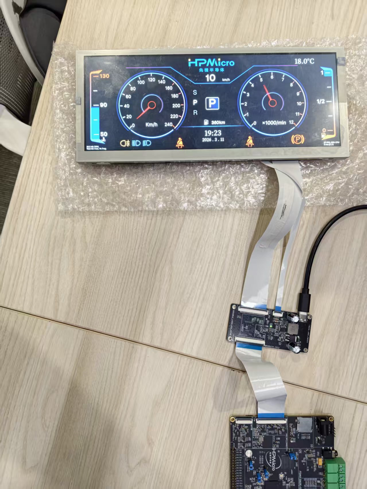
This solution is based on the HPMicro HPM6800EVK platform and combines LVGL, FreeRTOS, LCDC, and PDMA to implement a multi-layer dashboard demo project for digital instrument cluster scenarios.
Unlike traditional UI solutions based on full-screen redraw, this project splits the dashboard into 1 full-screen base layer + 7 local hardware overlay layers, for a total of eight layers. Large static backgrounds and low-frequency elements remain on the main layer, while high-frequency changing elements such as the dual pointers, left and right energy bars, top turn indicators, bottom warning bar, and central gear area are placed on separate layers. This reduces unnecessary refresh area, lowers memory bandwidth pressure, and improves animation smoothness.
This solution mainly demonstrates the following:
Eight-layer dashboard architecture: splitting UI regions based on the LCDC’s 8-layer capability
Layered rendering strategy: drawing static content separately from high-frequency dynamic content
Optimized buffer design: using different buffer strategies for the main layer and sub-layers
PDMA flush pipeline: using PDMA to transfer dirty regions and reduce CPU involvement
23.3. Key Features
23.3.1. Multi-layer Display Features
Parallel composition of eight hardware layers: one main background layer plus 7 transparent
ARGB8888overlay layersIndependent layer refresh: different regions are output to the LCDC independently at their own update rates
Transparent blended display: each layer is composited into the final image using
src_overblending modeDedicated local layers for local regions: high-frequency animated widgets are constrained to smaller rectangular regions
23.3.2. Dynamic UI Features
Dual gauge pointer animation: the speedometer and tachometer pointers are refreshed independently
Left/right energy bar animation: the vertical bar regions on both sides are updated independently
Alert/indicator animation: turn signals, fog lights, high/low beam, seatbelt, handbrake, and similar icons are controlled independently
Gear roller and value display: the center area is split into its own layer to avoid affecting the whole screen
Time/temperature/range information display: shown on the main layer as static or low-frequency widgets
23.3.3. Rendering and Performance Features
Main layer direct render: the full-screen main display uses
LV_DISPLAY_RENDER_MODE_DIRECTSub-layer full render: local layers use
LV_DISPLAY_RENDER_MODE_FULLDouble buffering: the main layer and all 7 sub-layers use double buffering
PDMA dirty-region transfer: during main-layer flush, only dirty regions are copied into the LCDC scan buffer
D-Cache coordination: writeback / invalidate is performed before and after CPU/DMA access to shared memory
23.4. Hardware Requirements
23.4.1. Main Control Board Requirements
MCU:
HPM6800EVKDisplay Output:
1920 x 720dashboard interfaceDisplay Controller: on-chip
LCDCDMA Acceleration: on-chip
PDMARuntime Memory: large
SDRAMis required to hold multiple groups ofARGB8888frame buffers
23.5. Device Connection
23.5.1. Hardware Connection Diagram
23.6. Create the Project
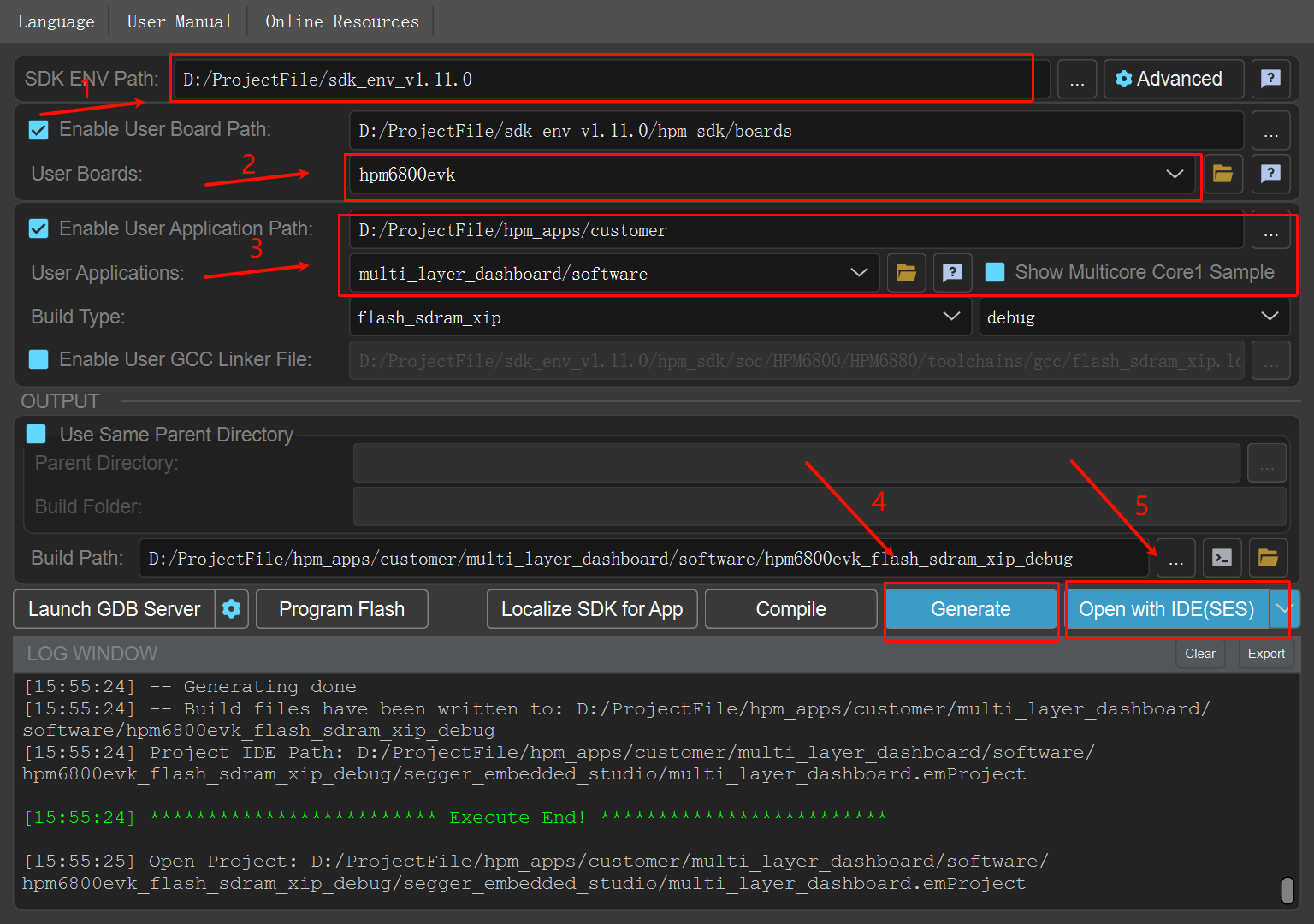
23.6.1. Software Components
LVGLFreeRTOShpm_panelLCDCdriverPDMAdriver
23.7. Software Architecture
23.7.1. System Framework
┌──────────────────────────────────────────────┐
│              Dashboard UI Layer              │
│   (background, pointers, gear, alerts, energy bars, etc.) │
└────────────────┬─────────────────────────────┘
                 │
┌────────────────┴─────────────────────────────┐
│           LVGL Multi-Display Layer           │
│   (main layer Direct Render + sub-layer Full Render)      │
└────────────────┬─────────────────────────────┘
                 │
┌────────────────┴─────────────────────────────┐
│         PDMA + D-Cache Coherency             │
│   (dirty-region transfer + cache writeback/invalidate)    │
└────────────────┬─────────────────────────────┘
                 │
┌────────────────┴─────────────────────────────┐
│            LCDC Hardware Compose             │
│   (8 hardware layers + alpha blend output)   │
└──────────────────────────────────────────────┘
23.7.2. Task Structure
LVGL refresh task: repeatedly calls
lv_timer_handler()to drive the UI and animationsDisplay output pipeline: LCDC is responsible for final compositing of the main layer and the 7 local layers
VSYNC synchronization pipeline: LCDC interrupts are used for refresh synchronization and display switch confirmation
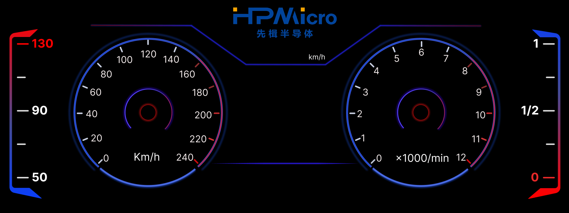
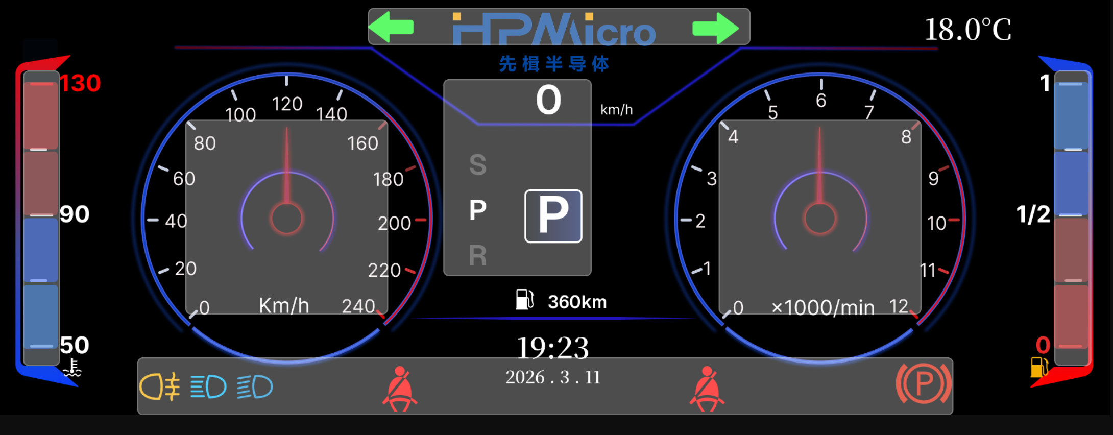
23.8. Eight-layer Design
23.8.1. Layer Design Illustration
Background layer illustration:
Layer split illustration:
Effect GIF:
23.8.2. Layer Allocation Description
This project uses a total of 8 hardware display layers, including 1 full-screen main layer and 7 local overlay layers. In the code, the main layer is initialized in user_lvgl_port.c, and the local layers are initialized individually in ui/screens/home_gen.c.
Hardware Layer |
Software Object |
Region Size |
Main Content |
Design Purpose |
|---|---|---|---|---|
Layer 0 |
Main display |
|
Background image, engine icon, fuel/water temperature icons, date, time, temperature, range, etc. |
Carries the full-screen background and low-frequency refresh elements |
Layer 1 |
|
|
Left speedometer pointer |
Offloads the high-frequency rotating pointer from the main layer |
Layer 2 |
|
|
Right tachometer pointer |
Refreshes the other high-frequency pointer independently |
Layer 3 |
|
|
Left vertical energy bar |
Refreshes only the left bar region |
Layer 4 |
|
|
Right vertical energy bar |
Refreshes only the right bar region |
Layer 5 |
|
|
Bottom warning/light icon strip |
Centrally manages bottom status icons |
Layer 6 |
|
|
Top left/right turn indicator icons |
Separately implements blinking animation |
Layer 7 |
|
|
Center speed value, gear roller, gear labels |
Independently refreshes the center interaction area |
23.8.3. Layer Splitting Principles
High-frequency animations are placed on separate layers: the speed pointer, tachometer pointer, and left/right energy bars are all high-frequency update objects
Objects with the same semantics are grouped into the same layer: bottom status lights are grouped into one horizontal layer, and top turn indicators are grouped into another dedicated layer
Keep the main layer stable: background, time, temperature, and other low-frequency elements stay on the main layer to reduce full-screen redraws
Minimize the region size: each sub-layer uses a bounding-box-sized region as much as possible to reduce double-buffer cost per layer
23.9. Rendering Strategy
23.9.1. 1. The Main Layer Uses Direct Render
The following are enabled in software/inc/lv_app_conf.h:
LV_USE_HPM_MODE_DIRECT = 1LV_USE_HPM_PDMA_FLUSH = 1
The main layer is configured in software/src/user_lvgl_port.c through:
lv_display_set_buffers(disp, user_lvgl_fb0, user_lvgl_fb1, USER_LVGL_FB_SIZE, LV_DISPLAY_RENDER_MODE_DIRECT)
This configures it as a Direct Render double-buffer mode.
The meaning of this design is:
LVGL directly organizes the final main-layer image in the full-screen draw buffer
When multiple dirty regions exist, there is no need to maintain a complex local buffer layout for each small region
In a dashboard scenario with a large background and a small amount of dynamic updates, this works well with PDMA dirty-region transfer
23.9.2. 2. Main-layer Flush Uses PDMA to Transfer Dirty Regions
The strategy of the main-layer flush callback user_lvgl_display_flush_cb() is:
First accumulate the dirty regions reported by LVGL
Perform D-Cache writeback on draw-buffer data corresponding to the dirty regions
Use
PDMAto copy the dirty regions frompx_maptouser_lvgl_lcdc_fbCall
lv_display_flush_ready()after the transfer is completed
The benefits of this approach are:
Reduced CPU per-pixel copy overhead
Reduced risk of display jitter caused by directly switching full-screen buffers
Balances the development convenience of Direct Render with the stability of the LCDC scan buffer
23.9.3. 3. Sub-layers Use Full Render
All 7 local layers are created as follows:
lv_display_create(width, height)lv_display_set_color_format(..., LV_COLOR_FORMAT_ARGB8888)lv_display_set_buffers(..., buf0, buf1, sizeof(buf0), LV_DISPLAY_RENDER_MODE_FULL)
The reasons for choosing FULL mode are:
The sub-layers are much smaller than the full screen, so full-layer redraw cost is controllable
The logic is simpler, because during flush it only needs to switch the next frame buffer for that layer
Local layers usually correspond to a single functional area and naturally fit a full-layer update model
23.9.4. 4. LCDC Handles the Final Multi-layer Composition
Each sub-layer is configured as follows:
Pixel format:
ARGB8888Transparent background:
lv_obj_set_style_bg_opa(..., LV_OPA_TRANSP, 0)Blend mode:
display_alphablend_mode_src_over
Therefore, LCDC finally blends the main layer and each local layer in real time according to the hardware layer hierarchy, avoiding repeated software full-screen composition.
23.10. Buffer Selection and Design
23.10.1. Main-layer Buffers
The main layer uses 3 groups of full-screen buffers:
user_lvgl_fb0: LVGL drawing buffer 0user_lvgl_fb1: LVGL drawing buffer 1user_lvgl_lcdc_fb: the actual LCDC scan-out buffer
Among them:
user_lvgl_fb0 / user_lvgl_fb1form the double-buffered drawing surfacesuser_lvgl_lcdc_fbacts as the stable foreground display surfacePDMA copies dirty regions from the current drawing buffer to the scan buffer, balancing performance and display stability
23.10.2. Sub-layer Buffers
Each sub-layer allocates two independent buffers, for example:
layer2_buf0/layer2_buf1layer3_buf0/layer3_buf1…
layer8_buf0/layer8_buf1
These buffers share the following characteristics:
Placed in the
.framebuffersectionAligned to
HPM_L1C_CACHELINE_SIZEUnified pixel format:
ARGB8888During flush,
lcdc_layer_set_next_buffer()is used to switch to the next frame
23.10.3. Why This Buffer Selection
The main layer is large: it is better suited to Direct Render + PDMA dirty-region copy
The sub-layers are small: they are better suited to Full Render + independent double-buffer flipping
Each layer is independent: one local animation does not force other layers to redraw
Bandwidth is more controllable: high-frequency animations consume bandwidth only on the corresponding sub-layer
The structure is clearer: display issues are easier to locate and debug layer by layer
23.11. Run-time Behavior
23.11.1. After System Startup
After startup, you can see a typical digital dashboard interface including:
Center speed numeric display
Left and right circular gauge pointer animations
Dynamic changes of the left and right vertical energy bars
Blinking left and right turn indicators at the top
Status display for bottom light / seatbelt / handbrake and other icons
Center gear roller and gear label switching
23.11.2. Animation Behavior
The speed and tachometer pointers can rotate smoothly
The top turn indicators blink according to a timer rhythm
The bottom warning icons can be shown or hidden by group
The left and right energy bars animate their height and color independently
23.12. Solution Value
23.12.1. Applicable Scenarios
Automotive instrument clusters
Smart cockpit HMIs
Display systems that require optimization through hardware overlay composition
23.12.2. Design Benefits
Reduced full-screen refresh pressure
Improved animation smoothness
Reduced unnecessary pixel transfer
Better suited to high-resolution
ARGB8888display scenariosMore convenient for later extension with additional local dynamic widgets