24. EtherCAT Master-Based Integrated Display and Control Solution for Motors
24.1. Depends on SDK 1.11.0
24.2. Overview
This solution is built on HPM series MCUs from HPMicro, integrating EtherCAT master technology and the LVGL graphics interface to provide a complete EtherCAT master motor control solution.
This solution integrates the following core capabilities:
EtherCAT Master: Industrial-grade EtherCAT master based on open-source CherryECAT
CIA402 Motor Control: Supports CSP (Cyclic Synchronous Position) and CSV (Cyclic Synchronous Velocity) motion control modes
LVGL UI: Intuitive touch-screen control interface with real-time display of motor status and motion parameters
FreeRTOS: Ensures real-time performance and stability for motor control
Shell CLI: Supports command-line debugging and configuration
24.3. Core Features
24.3.1. EtherCAT Master Features
Asynchronous Queue Transfer: One transfer can carry multiple datagrams
Zero-Copy Technology: Directly uses Ethernet TX/RX buffers
Hot-Plug Support: Automatically scans the bus and updates slave info when topology changes
Automatic State Monitoring: Real-time monitoring of slave status
24.3.2. Motor Control Features
CIA402 Standard Protocol: Compliant with industrial standard motor control interfaces
Multiple Control Modes:
CSP (Cyclic Synchronous Position)
CSV (Cyclic Synchronous Velocity)
Device Switching: Supports switching control between multiple motor devices
Real-Time Feedback: Real-time display of position, velocity, and status
Fault Diagnostics: Connection state monitoring and error indication
24.3.3. UI Features
Modern Design: Smooth touch interface based on LVGL v9
Speed Control: Arc slider to adjust target speed
Position Control: Arc slider to adjust target position
Real-Time Waveform: Chart component showing motion curves
Device Management: Supports multi-device selection and status display
Button Controls: Quick actions for start/stop and forward/reverse
24.4. Hardware Requirements
24.4.1. Controller Board Requirements
MCU: HPM6800EVK
Display: 1280x800 resolution touch screen
Ethernet: Interface supporting EtherCAT communication
Debug Interface: JTAG/SWD
Serial Port: UART
24.4.2. Slave Device Requirements
EtherCAT servo drives supporting CIA402 protocol
24.5. Software Architecture
24.5.1. System Framework
┌─────────────────────────────────────────┐
│         LVGL UI Layer                   │
│  (Touch Control + Real-time Display)    │
└─────────────┬───────────────────────────┘
              │
┌─────────────┴───────────────────────────┐
│      Application Layer                  │
│  (CIA402 Control Logic + Data Handling) │
└─────────────┬───────────────────────────┘
              │
┌─────────────┴───────────────────────────┐
│      CherryECAT Master                  │
│  (PDO Comm + DC Sync + State Machine)   │
└─────────────┬───────────────────────────┘
              │
┌─────────────┴───────────────────────────┐
│      FreeRTOS + Ethernet Driver         │
│  (Task Scheduling + Network Driver)     │
└─────────────────────────────────────────┘
24.5.2. Task Structure
LVGL Task: UI refresh and touch event handling
EtherCAT Task: Periodic PDO communication and status monitoring
Shell Task: Command-line interaction and debugging
24.6. Device Connections
24.6.1. Hardware Connection Diagram
[PC Debug Tool] ──USB──> [HPM Board] ──JTAG──> [Debugger]
                         │
                         │ EtherCAT
                         ├──> [Servo Drive 1] ──> [Motor 1]
                         │
                         ├──> [Servo Drive 2] ──> [Motor 2]
                         │
                         └──> [Servo Drive N] ──> [Motor N]
24.6.2. Connection Steps
Connect PC USB to board DEBUG Type-C interface
Connect debugger to JTAG interface
Connect EtherCAT slave devices (servo drives)
Connect motors to the drives
Connect display to the board (if using UI)
Power on the system
24.7. Port Settings
Baud Rate: 115200bps
Stop Bits: 1
Parity: None
Data Bits: 8
24.8. Project Creation
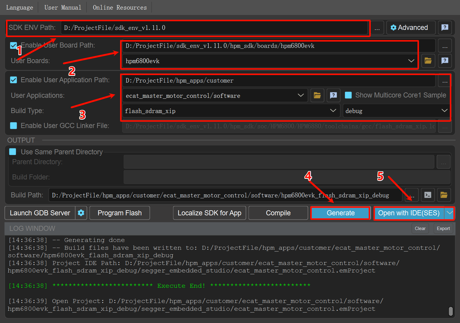
24.9. Runtime
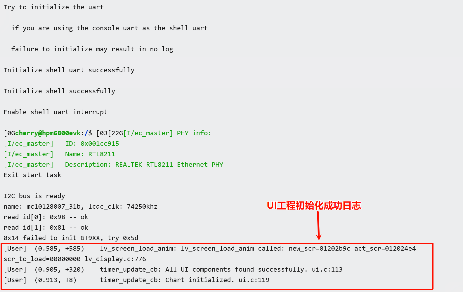
24.9.1. System Startup
24.9.1.1. Serial Log for Successful Project Initialization (No Slaves Connected):
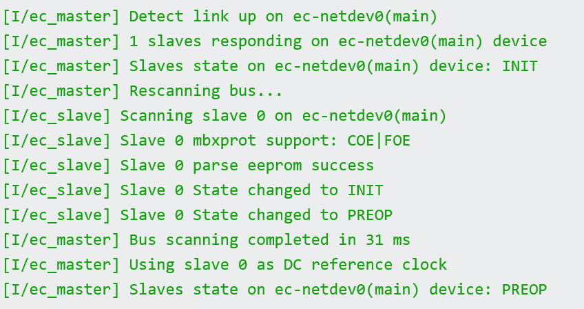
24.9.1.2. Serial Log for Successful Slave Connection:
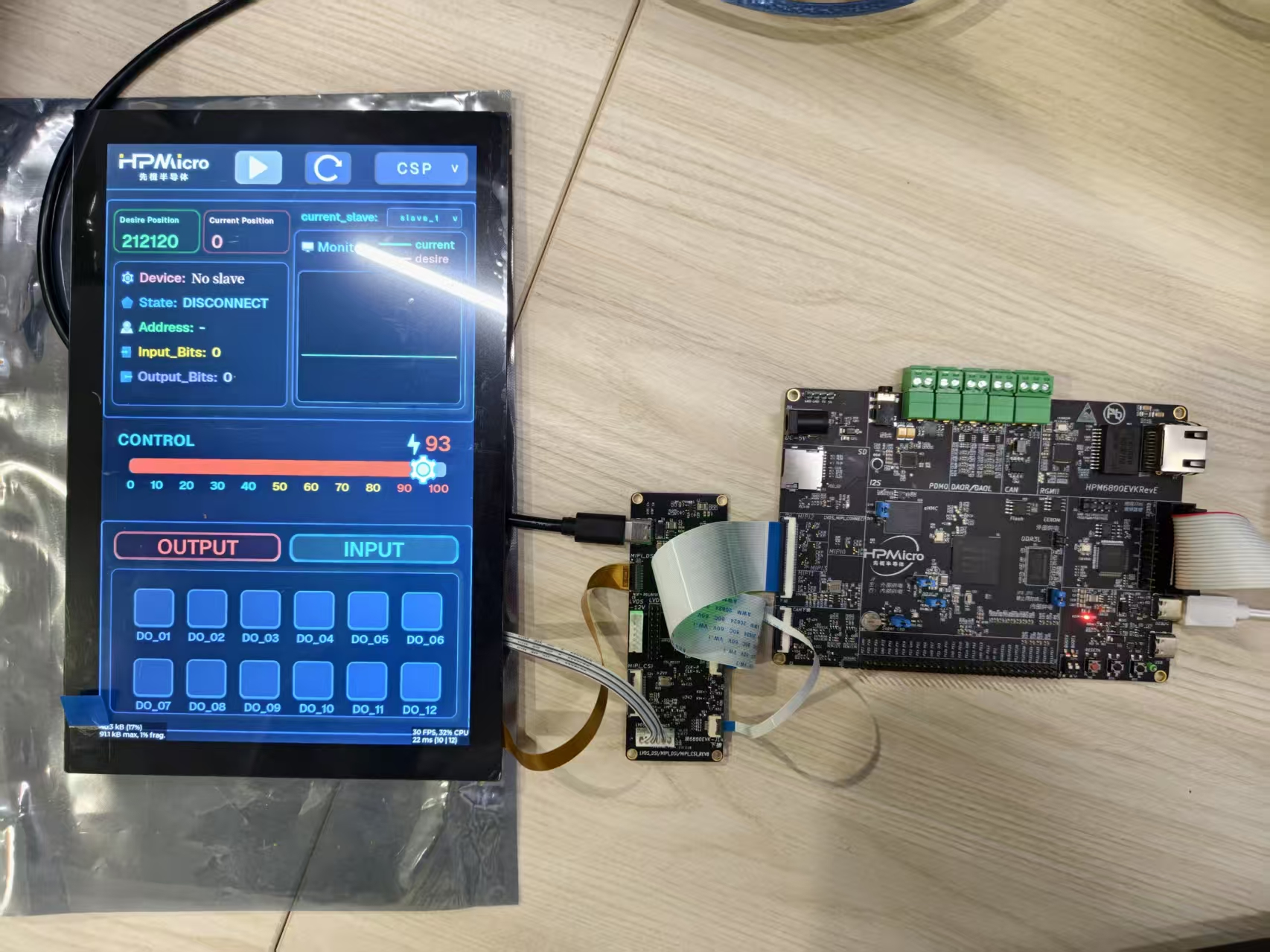
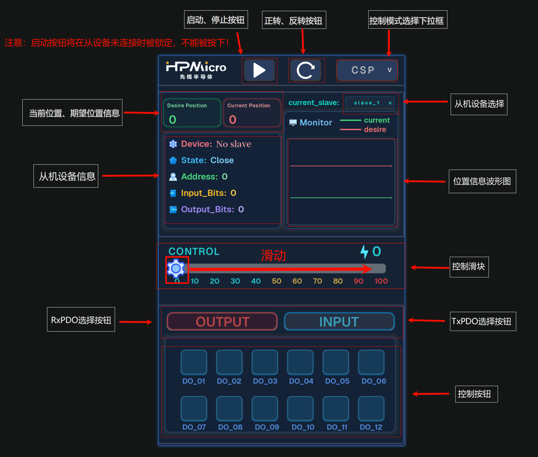
24.9.2. UI Display
The touch screen will display the motor control interface, including the following elements:
Top Status Bar:
HPMicro logo
Start button
Forward/Reverse buttons
Control mode dropdown box
Device Information Module:
Control Area:
Draggable slider (0-100)
Slide right to control speed or position
Real-time value display
Bottom In/Output Control Buttons:
INPUT mode selection button
OUTPUT mode selection button
12 bit input/output buttons
24.10. Features
24.10.1. 1. Device Management
Automatically scans all slaves on the EtherCAT bus
Supports hot-plug detection
Supports multi-device switching control
Real-time display of device count and current selection
24.10.2. 2. Control Exclusivity
Speed control and position control are mutually exclusive (only one mode can be active at a time)
Interface automatically switches to display corresponding slave device info
24.10.3. 3. Visual Feedback
Visual feedback when buttons are pressed
Waveforms for target and actual values are displayed in different colors
24.10.4. 4. Data Acquisition
Waveform chart displays motor motion status in real-time
Real-time display of slave status information