3. HPM6E_ROBOT3.0 solution
3.1. Depend on SDK1.11.0
3.2. Introduction
The HPM6E00 series MCU is a domestically produced high-performance, high real-time, mixed signal microcontroller with RISC-V core, designed as a motor control development platform for multiple industrial motor application scenarios. This platform provides a multi motor solution for the industrial field, with EtherCAT slave controllers that support up to three ports;Supports up to 16 channels of high-resolution PWM output; Has 2 QEI and 2 QEO interfaces; Support 4-channel Sigma delta signal receiving unit; Equipped with programmable logic module PLB; High performance analog peripherals that support up to 16 channels of 16 bit ADC inputs. The HPM6E_ROBOT_SERVO3.0 solution uses the HPM6E00 series chip as the main control chip and utilizes the self-developed closed-loop stepper motor algorithm library. The main functions of this solution are:
Support FOE, firmware upgrade can be done through EtherCat; Support CIA402 protocol, with CSP, CSV and other modes; Hardware current protection function; Voltage protection function; Speed protection function; Current loop parameter setting function; Inertia identification function; 3P3Z function; Support HPM Monitor Studio upper computer.
The input voltage of this scheme is 24V, the maximum output current is 13A, and the supported maximum speed is 900rpm. The motor adjustment parameters and required functions are open for users to debug and adapt to different motors.
3.3. Introduction to the hard solution of the plan
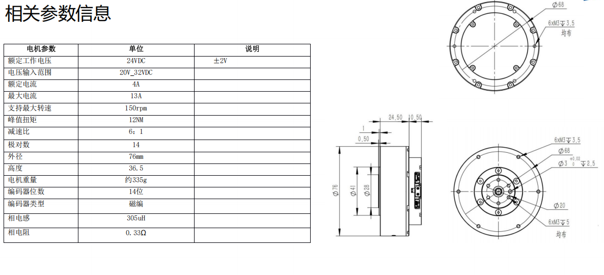
The motor used in the plan is Damiao DM-J6006-2EC

Main interface description:
24V power interface: power supply, maximum current above 1A;
EtherCAT OUT: Used for cascading ECAT slave devices to the next level;
EtherCAT IN: Connected to the upper computer, TwinCAT is used as the upper computer for this test;
UART serial port, used for debugging and connecting to HPM Monitor upper computer;
JTAG interface, used for debugging and burning. During testing, the boot firmware needs to be burned to the MCU through this interface.
3.4. Software and hardware required for scheme testing
Before using this solution, it is necessary to prepare some necessary hardware and software.
First, the SDK 1.11.0 and HPM APPS 1.11.
24V power supply, maximum current above 1A.
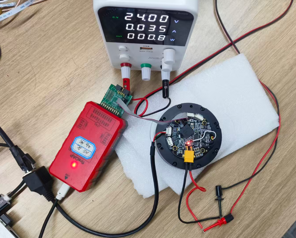
Wiring preparation: The motor model used in the routine is Damao DM-J6006-2EC, and the EtherCAT IN interface is connected to the Ethernet cable through an adapter, Then connect to a computer with TwinCAT software installed, and the wiring of the motor is shown in the following figure:
A computer with TwinCAT and Python environment installed (for packaging user bin files);
One Ethernet cable;
JTAG debugger or TYPE-C cable;
Place the ECATFOE_CIA402 configuration file (in the tool folder of the solution) in the TwinCAT directory: TwinCAT \ 3.1 \ Config \ Io \ EtherCAT.
3.5. Project software structure
The software file structure of HPM6E-ROBOT_SRVO3.0 scheme is shown in the following figure:

The doc folder contains the documentation of the plan, including the design plan and usage guide. The hardware folder contains the schematic diagram of the solution. The software folder contains the software code for the solution, including bootuser and user’app. The tools folder contains serial assistant, network assistant, firmware packaging tool (requiring Python environment), and the XML configuration files required for this solution. Figure 4-2 shows the directory structure of the software folder, where bootuser and user’app are two independent projects. The bootuser folder is for the firmware upgrade function project in non background download mode; The common folder contains the common code for two projects, including enet, ethercat, USB, and UART. Ethercat is used for firmware upgrade in this solution; The linker folder contains linker files related to supported chips, and this solution uses the HPM6E6Y chip; The user’app folder contains the project files used by the user, and users can add/modify functions within this folder.
3.6. Test
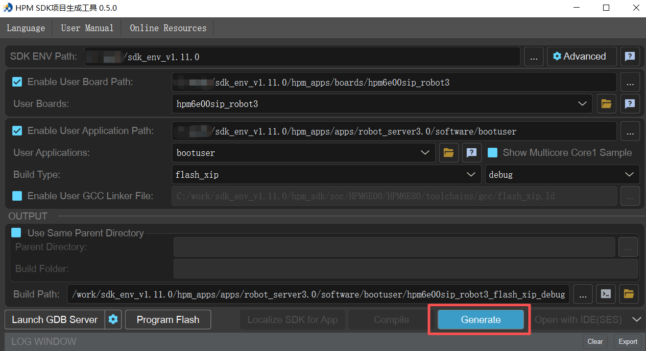
First, build a boot project
3.6.1. boot project build
According to the functionality of the plan, the testing is divided into the following parts:
3.6.2. FOE functional testing
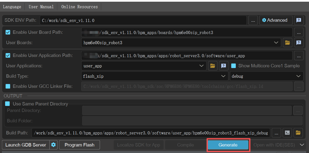
(1)app project build
(2)Create upgrade package
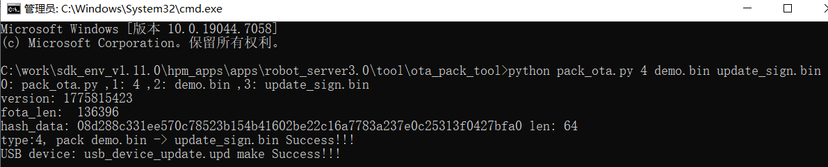
Place the generated app firmware in the tool \ ota_cack_tool folder of the project, and open the cmd command window in the ota_cack_tool folder,
Run command: python pack_ota-py 4 demo.bin update_stign.bin, the packaged bin file is update_stign.bin.
(3)Upgrade using TwinCat
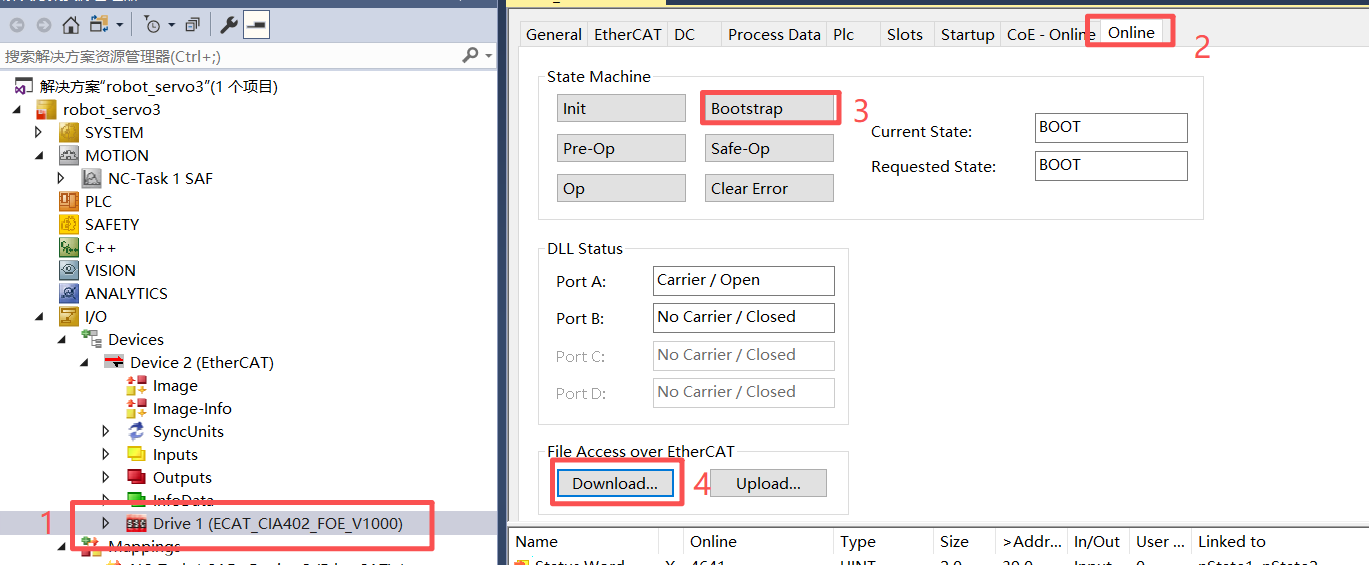
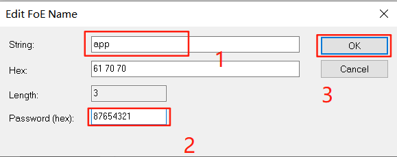
Please note that the firmware name must be app and the password must be 87654321, which cannot be changed to any other value.
3.6.3. CIA402 Function Test
Divided into two parts, CSV mode and CSP mode.
(1)CSV mode testing
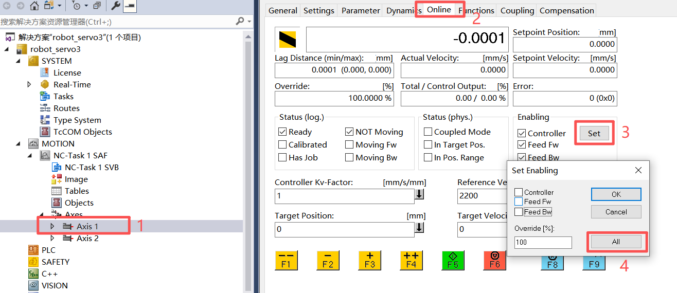
After the device is connected to the TwinCat upper computer, it defaults to CSV mode. After setting the DC mode, simply set the target position and target speed.
 (2)CSP mode testing
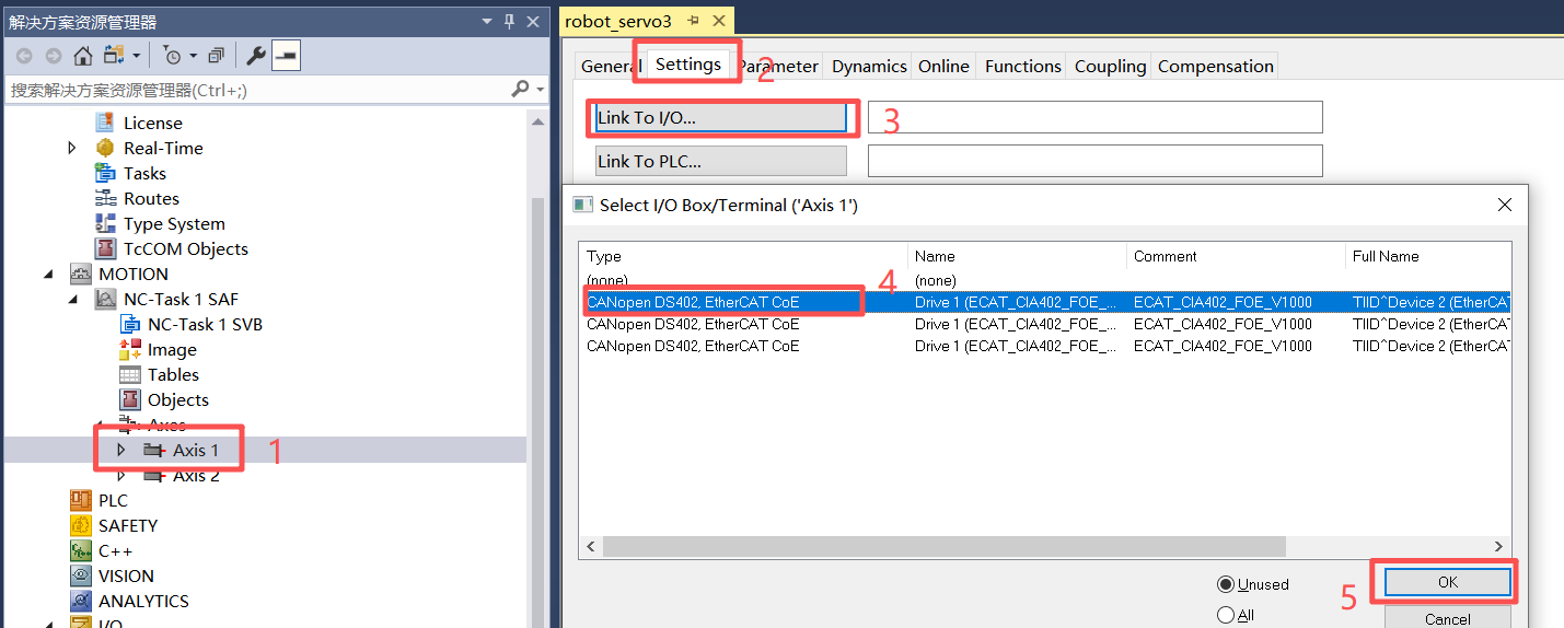
After switching from CSV to CSP mode, it is necessary to re link the devices and reset the target position and target speed.
(2)CSP mode testing
After switching from CSV to CSP mode, it is necessary to re link the devices and reset the target position and target speed.
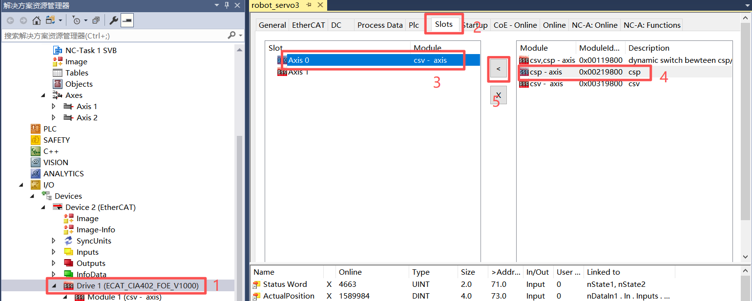 After switching modes, reconnect the device as shown in the following figure:
3.6.4. Current loop parameter tuning test
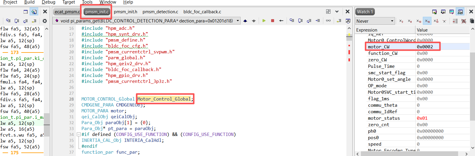
The use of this feature requires online debugging using JLINK or DAPLINK. After downloading the user’app project to the MCU, add the motor control global variable Motor_Control Global from the pmsm_init. c file to the watch,
Modify motor_CW in the structure to 2.
At the last break point of the pi_ params_get function in the pmsm_detection. c file, click the run button, and after the tuning is complete, hover the mouse over the variables kp and ki to see the tuning result. The result can also be printed out through the serial port.
3.6.4.1. Inertia identification function test
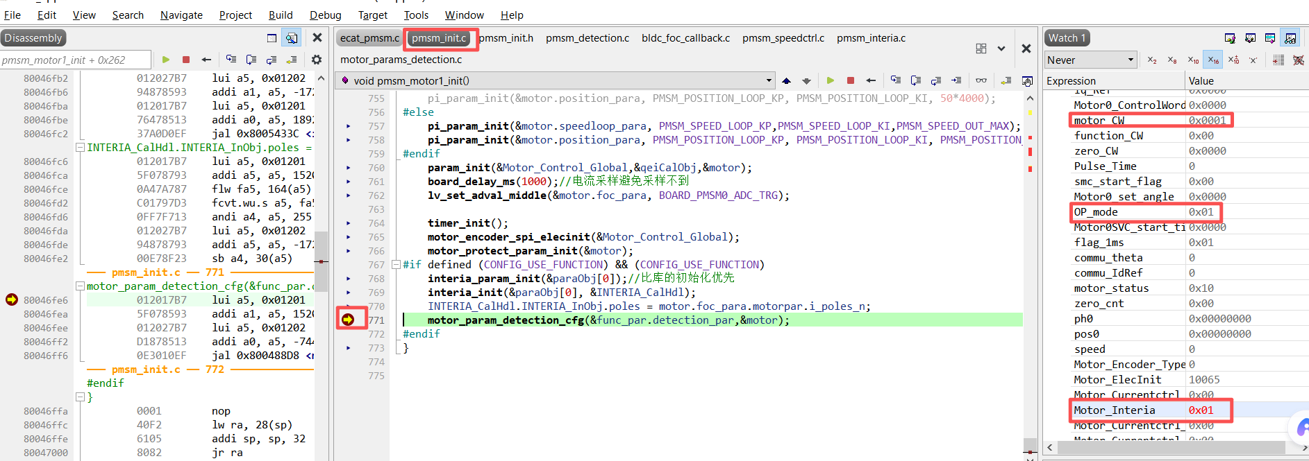
The use of this feature requires online debugging using JLINK or DAPLINK. First, set the macro definition MOTORCONTROL_EC_OR_STUDIO in board. h to 1 to disable the EtherCat function. After downloading the user’app project to the MCU, add the motor control global variable Motor_Control Global from the pmsm_init. c file to the watch to prevent modification of the global variable during initialization, First, at the last break point of the pmsm_motor1_nit function, modify motor_CW to 1, OP_rode to 1, and Motor_interia to 1 in the structure.
 Add the inertia identification global variable INTERIA_CalHdl from the pmsm_init. c file to watch, run for about 30 seconds, and at the last break point of the motor_interiactrl function in the pmsm_interia. c file,
By checking the INTERIA_CalHdl variable, the results of inertia identification can be seen.
Add the inertia identification global variable INTERIA_CalHdl from the pmsm_init. c file to watch, run for about 30 seconds, and at the last break point of the motor_interiactrl function in the pmsm_interia. c file,
By checking the INTERIA_CalHdl variable, the results of inertia identification can be seen.
3.6.4.2. 3P3Z functional testing
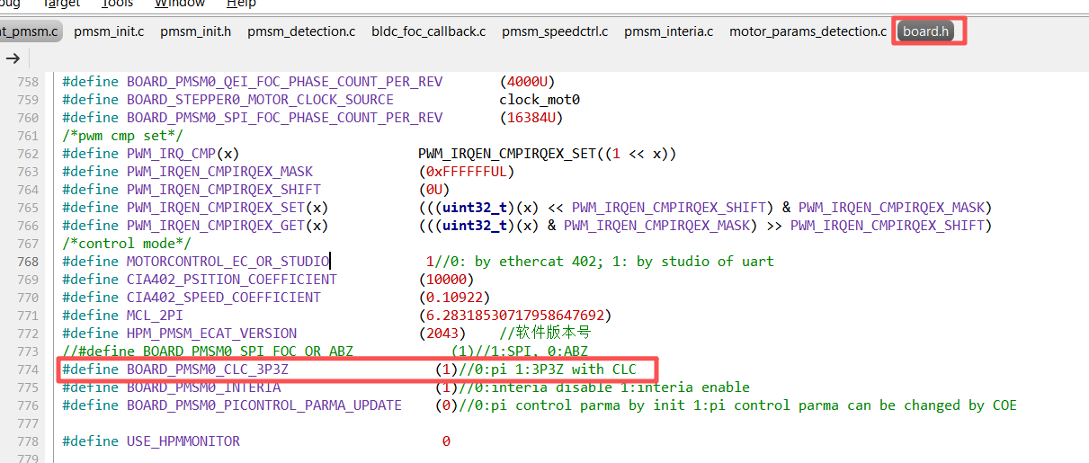
This scheme defaults to using the 3P3Z function. If the user does not use the 3P3Z function, they only need to change the macro definition BOARD_PMSM0_CC3P3Z in board. h to 0.
3.6.4.3. HPM Monitor Function Test
HPM Monitor is a real-time monitoring tool for MCU launched by Xianji Semiconductor, which can display the values and dynamic curves of variables in real time and modify the values of variables. The HPM Monitor upper computer version used is HPMicroMonitorStudio1.2.1.
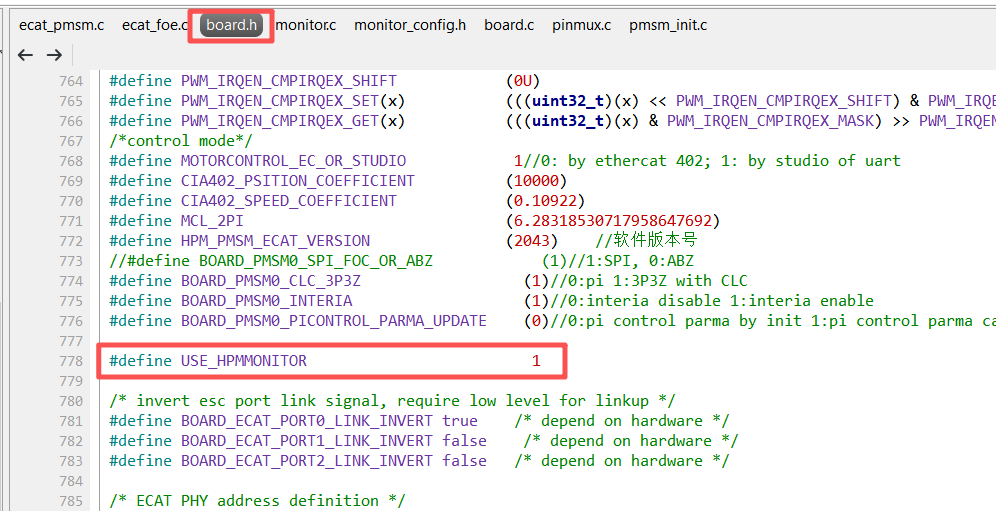
Change the USE-HPMMONITOR macro definition to 1 in bldc. h and default to 0. Burn new firmware through JTAG or upgrade firmware through FOE.
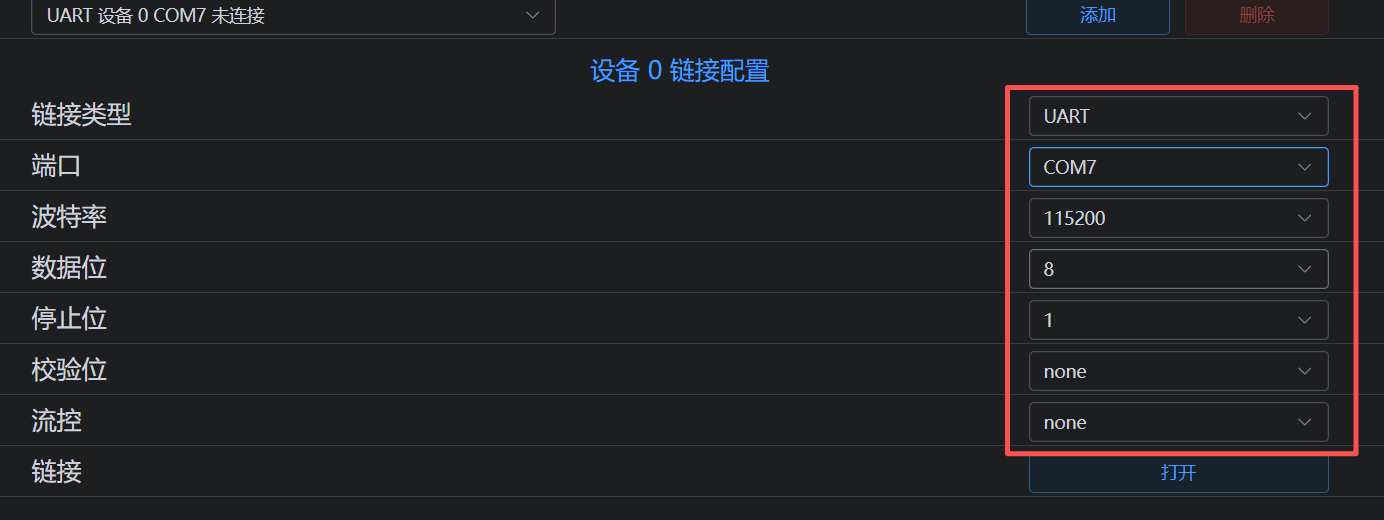
 The upper computer is connected to the circuit board through UART.
3.7. API
About software API: API doc 。