|
HPM APP
HPMicro Application solution
|
|
HPM APP
HPMicro Application solution
|
HPM6200 is a 32-bit high performance microcontroller based on RISC_V kernel from Shanghai HPM Semiconductor Technology Co., LTD.
For HPM6200 series MCUS, HPM Semiconductor has introduced a four-axis servo-drive solution, which adopts FOC control for single axis and synchronizes timer to realize four-axis motor movement with fixed phase difference.
The software design is mainly divided into four parts: pre-positioning, speed/position loop, current loop, S curve, synchronization timer, serial communication and USB communication.
The following table lists the global parameters.
| name | explain | type | |
|---|---|---|---|
| PI params | SPEEDLOOP_KP | speed loop gain | define |
| PI params | SPEEDLOOP_KI | speed loop integral | define |
| PI params | SPEEDLOOP_OUTMAX | speed loop maximum output | define |
| PI params | POSITIONLOOP_KP | position loop gain | define |
| PI params | POSITIONLOOP_KI | position loop integral | define |
| PI params | POSITIONLOOP_OUTMAX | position loop maximum output | define |
| operation mode | OpMode_Typ | speed:1 position:0 | enum |
| velocity trajectory planning | CONSTANT_SPEED_TIME_s | constant speed time | define |
| velocity trajectory planning | MOVE_SPEED | velocity r/s | define |
| velocity trajectory planning | MOVE_ACC | acc r/s/s | define |
| velocity trajectory planning | MOVE_JERK | jerk r/s/s/s | define |
| position trajectory planning | MOVE_RELATIVE_POS_r | relative position r | define |
| position trajectory planning | CYCLE_CNT | cycle count | define |
| position trajectory planning | CONTINOUS_RONUD_MOVE_TYPE | contious round move type | define |
| position trajectory planning | SIGNLE_MOVE_TYPE | single move type | define |
| position trajectory planning | MULTIPLE_MOVE_TYPE | multiple move type(Choose one of the above three) | define |
| position trajectory planning | DWELLTIME_ms | dwell time | define |
| global control params | MOTOR_CONTROL_Global | struct | |
| motor params | MOTOR_PARA | struct |
The specific function interfaces are shown in the following table.
| API name | description | calling state |
|---|---|---|
| pwm_sync | synchronous timer | init |
| pmsm0_foc_angle_align | axis 0 presets | servo start |
| motor0_highspeed_loop | axis 0 current loop | 50us interrupt |
| pos_cmd_gene | position trajectory planning | 1ms interrupt |
| vel_cmd_gene | velocity trajectory planning | 1ms interrupt |
| motor_speed_ctrl | velocity/position loop | 1ms interrupt |
During power-on, the position of the motor rotor is random, and there is a fixed Angle difference between the position of the encoder rotor and the motor rotor. Therefore, it is necessary to turn the motor rotor position to a fixed position, at which time both the encoder position and the rotor Angle are known. In this scheme, the encoder rotor position coincides with the motor rotor position before normal operation.
The main implementation steps are divided into three steps:
The pwm channel generates a comparison interrupt that interrupts the current loop executed inside. Circuit loop loop has two main parts to work:
There is a step in the speed of the motor when it is started and stopped. A sudden change in motor speed can cause current overload. Therefore, the acceleration and deceleration control algorithm is usually used to plan the motor speed.
In this scheme, we use the trajectory planning algorithm in the motor library, S-curve, to control the change of acceleration through variable acceleration to ensure that acceleration does not mutate, so that the acceleration and deceleration speed curve is smooth and the motor runs more smoothly.
Here, take the motion axis 0 as an example to briefly introduce how to use the trajectory planning algorithm in the motor library:
(1) Add electrical hangar
For details, see the user guide of hpm_motor library (hpm_apps/middleware/hpm_motor/doc)
(2)assign a value to each member of the configuration parameter structure
CMDGENE_PARA cmdpar[4] = {0};
config cmdpar[0].cmdgene_in_par.velcfgpar
config cmdpar[0].cmdgene_in_par.poscfgpar
(3)trajectory generation
After axis 0 is enabled, the trajectory generation function is called within 1ms interrupt to obtain the speed instruction and position instruction of the corresponding time series
speed mode:vel_cmd_gene
position mode:pos_cmd_gene
(4)trajectory planning reset
API:cmd_gene_disable
Clear the intermediate variable of trajectory planning, so as to plan the starting point, end point and speed of the PTP movement specified by the user again, calculate the acceleration of the connected points, add the acceleration, and then calculate the position and speed of each point.
Timer generates 1ms interrupt, control speed loop/position loop update:
By configuring a synchronous trigger input SYNCI module connected to PWM, the four motors are turned on at a certain phase difference.
In order to facilitate user control of the motor, it supports issuing motion commands using UART or USB debugging tools. Users can choose to use UART or USB in the cmakelist file. The MCU performs corresponding movements based on the received motion instructions.
(1)test device
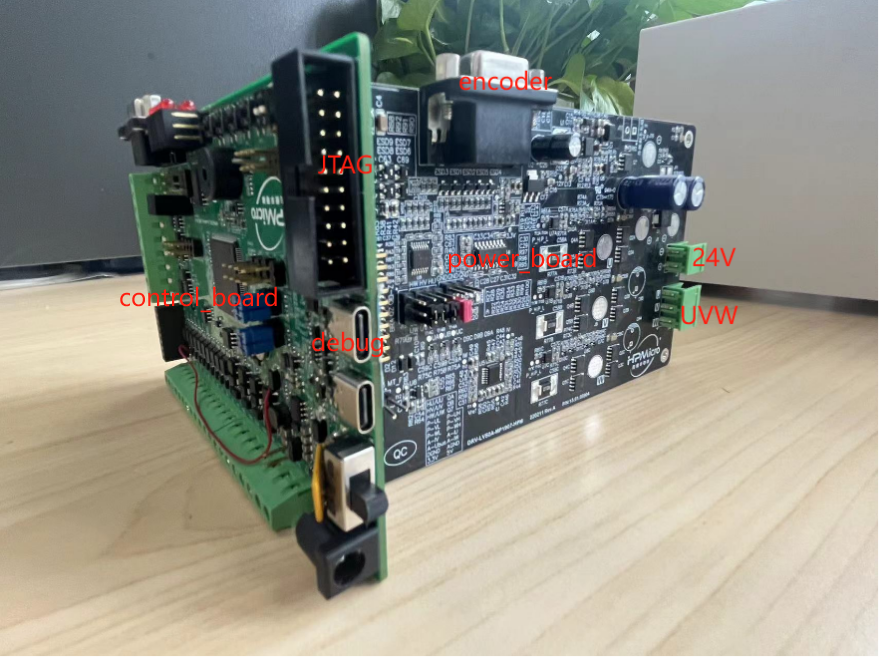
HPM6200 drive control hardware is composed of two boards, the control board is used to communicate with the serial port, debug, send PWM drive signal to the driver board and receive current sampling signal, encoder information.
The power board comprises a power drive module, a current sampling module, and contains an encoder, a motor and a power interface.
Four-axis drive control prototype picture is shown in the figure below.

Single-axis drive control picture is shown in the figure below.
(2)motor type
The test motor model information of this scheme is shown in the following table. If other motor models are selected, it is necessary to readjust the macro definition of PI control parameters.
| motor type | pairs of poles | encoder type | resolution |
|---|---|---|---|
| leisai BLM57050 | 2 | ABZ | 4000count/r |
(3)motion parameter
The default motion parameters are shown in the following table. For example, adjust the motion parameters and motion mode, and modify the macro definition according to the section "Configuration example"in hpm_motor libarary user guide.
| absolute position r | speed r/s | acc r/s/s | jerk r/s/s/s | trajectory planning mode |
|---|---|---|---|---|
| 20 | 10 | 100 | 1000 | S |
(4)device connection
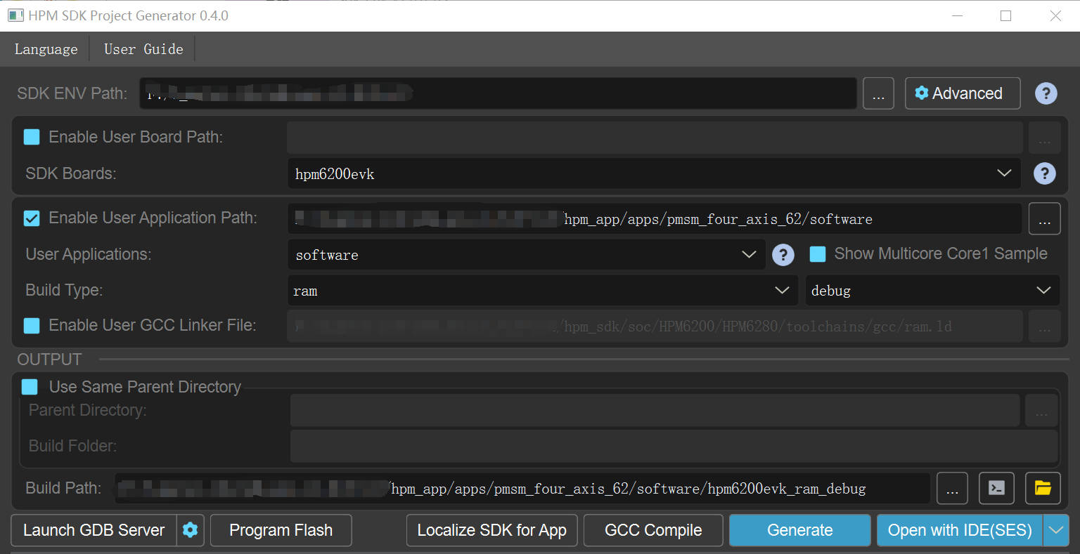
Double-click on the gui tool to create the project.
(1)compile and run the project successfully
(2)motor action, perform a predetermined position operation
(3)The serial port displays the following information:
(4)Using HPMicroMonitorStudio upper computer, select the motion axis and operation mode to control each motor
controlw_world [n] is set to 1, with a value range of n [0,3], the same applies below::
Op_rode [n] set to 0:Axis n in the speed mode runs with S-curve planning: speed accelerates from 0 to 10r/s at a constant speed for a period of time and then decelerates to 0
Op_rode [n] set to 1:In position mode, the absolute movement distance of axis n is 20r, and the continuous round-trip movement is carried out: the speed is planned by S-curve, accelerating from 0 to 10r/s at a constant speed for a period of time, then decelerating to 0, stopping 500ms, accelerating from 0 to -10r/s at a constant speed for a period of time, then decelerating to 0, stopping 500ms;
controlw_world [n] set to 0:
Axis n stops
HPM APP is permissively licensed using the BSD 3-clause license