|
HPM APP
HPMicro Application solution
|
|
HPM APP
HPMicro Application solution
|
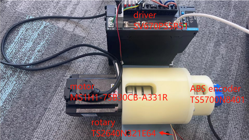
High performance motor control applications traditionally require a speed or position sensor for control loop feedback. The position feedback link has a critical impact on the performance of the system. Rotary transformers have become popular Angle sensors due to their advantages such as impact resistance, high temperature resistance, oil pollution resistance, high reliability, and long life.
At present, most of the existing rotary solutions in the market are discrete, with high BOM cost and large board area.
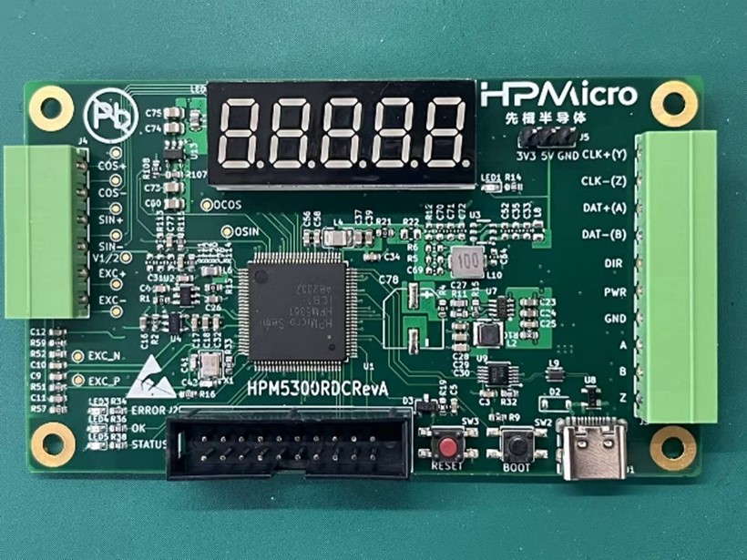
In order to simplify the design, HPM provides a functional rotary decode board integrating excitation op amp circuit, boost DC-DC chip, analog front end, rotary digital converter, rotary signal loss detection and multiple format data (position/speed) output interface.
HPM5300RDC board has the following functions: two ADC, one uart, one spi, two DAC, QEO output, SEI master/slave, LED display, etc.
HPM5300RDCschematic diagram: 《HPM5300_RDC_REVB》
The software solution is mainly composed of the following parts:
pwm generates the excitation signal, ADC samples it, and takes the envelope.
This scheme is divided into two parts:
(1) Hardware test: pwm modulated sinusoidal differential signal (EXC_P/EXC_N), rotary sinusoidal winding signal (OSIN/OCOS) (2) Functional test: Angle and speed observation
(1)Motor drive platform
(2)hHPM5300RDC
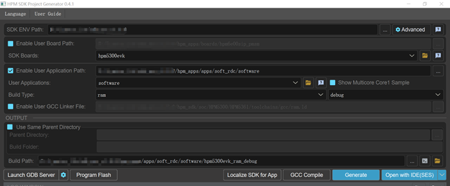
(1)HPM_RDC decoding software: soft_rdc (2) ozone (3) Jlink (4) RDC board pin description
| function | rotary plate location | note |
|---|---|---|
| EXC+ | J4[5] | rotary exc signal |
| EXC- | J4[6] | rotary exc signal |
| COS+ | J4[1] | rotary cos signal |
| COS- | J4[2] | rotary cos signal |
| SIN+ | J4[3] | rotary sin signal |
| SIN- | J4[4] | rotary sin signal |
| PWR | J3[5] | 24v,150mA |
| GND | J3[4] | GND |
| OEXC | R17 | |
| PWM | R16 | |
| sin | R16 |
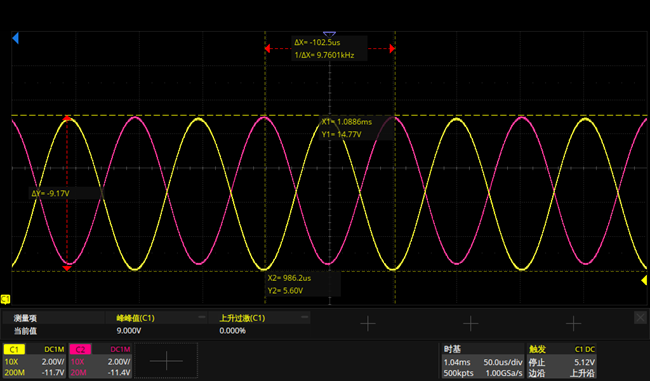
(1)static state:
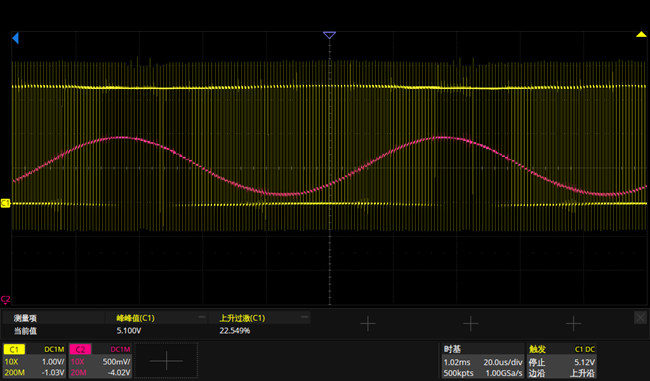
pwm modulated sinusoidal differential signal:EXC_P(yellow),EXC_N(pink)
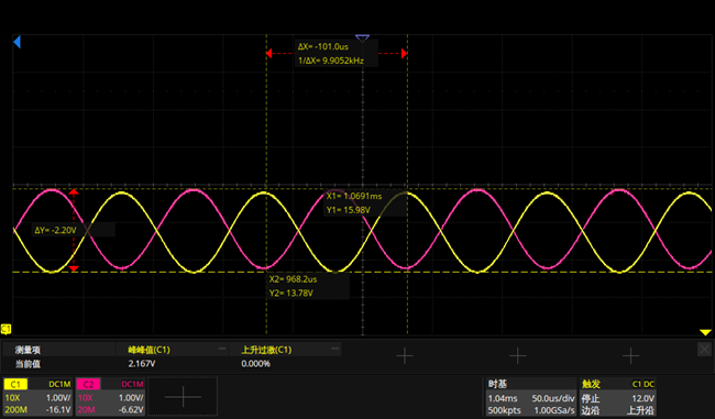
Sinusoidal differential signal after the amplifier output signal: EXC+,EXC-
OSIN(yellow),OCOS(pink)
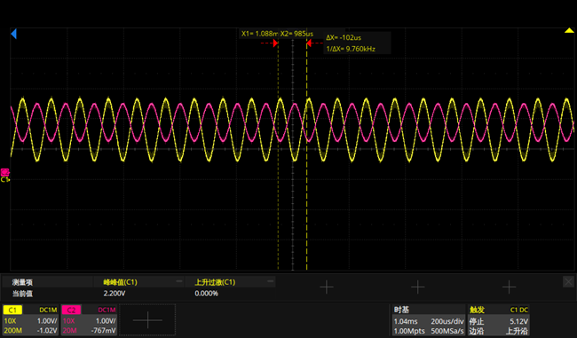
Differential EXC+- Transfer single end :OEXC(pink), osin(yellow)

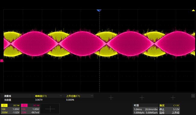
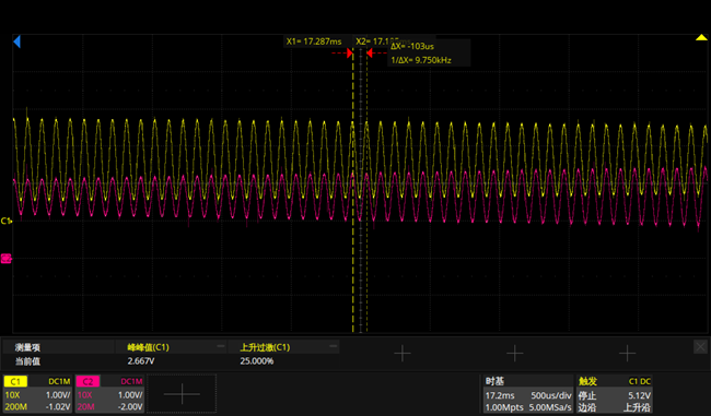
(2)In motion:
OSIN(yellow),OCOS(pink)
(3)1MhzSVPWM
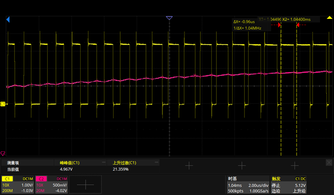
(4)1MhzADC sample
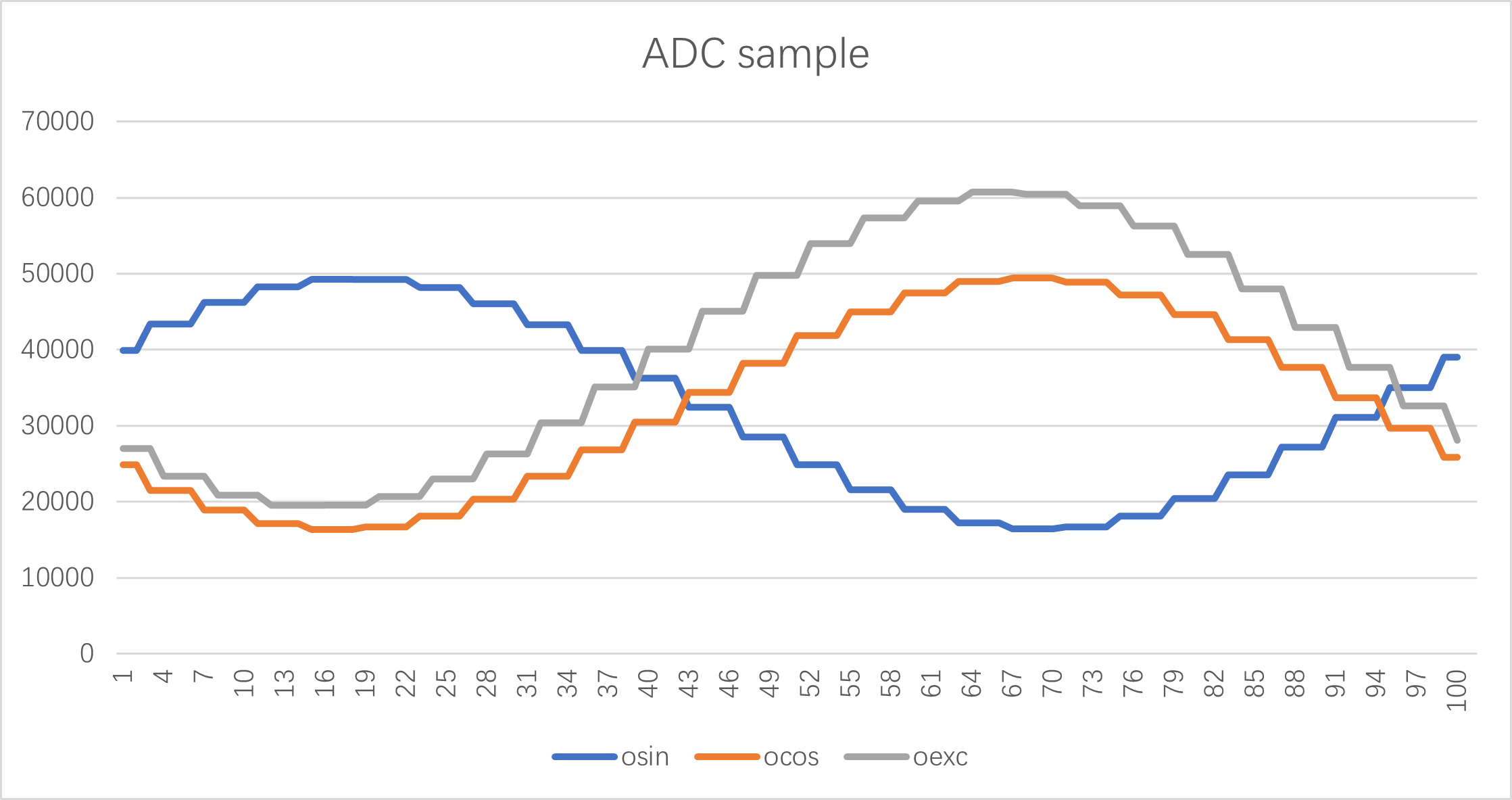
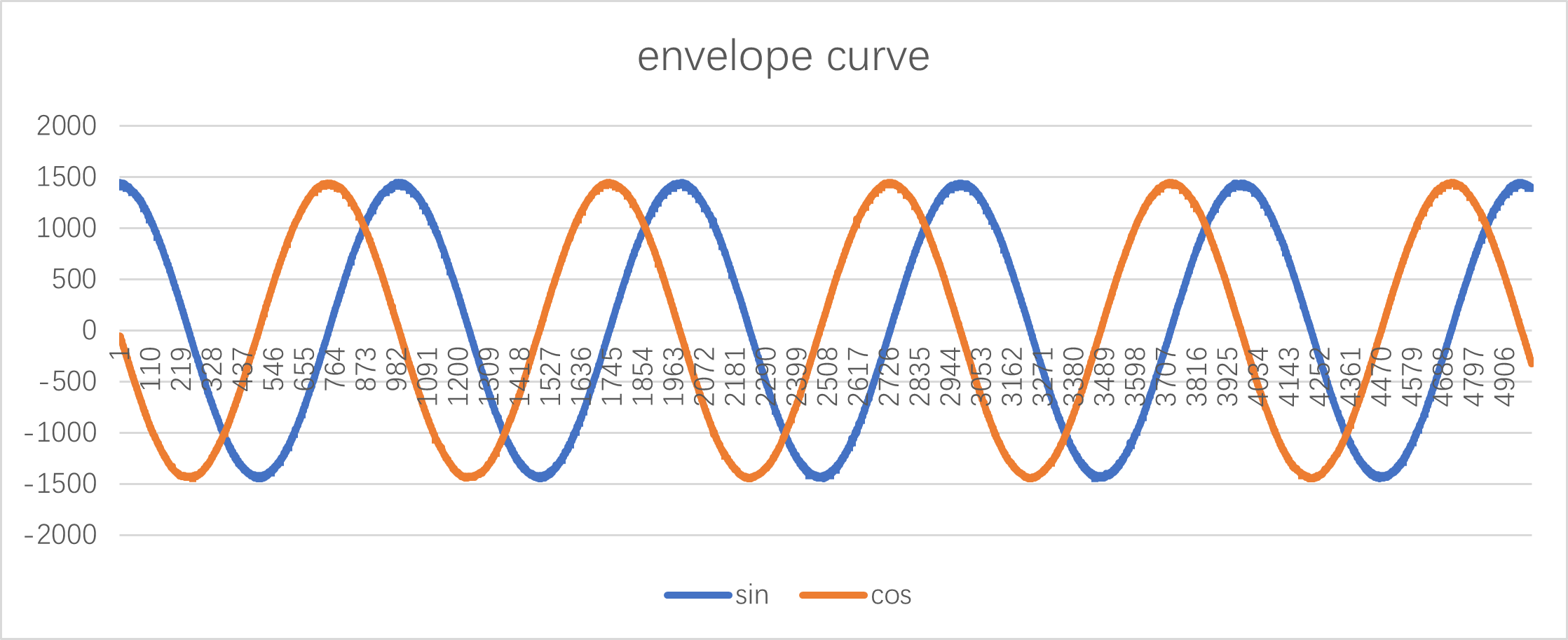
(5)envelope curve sin/cos
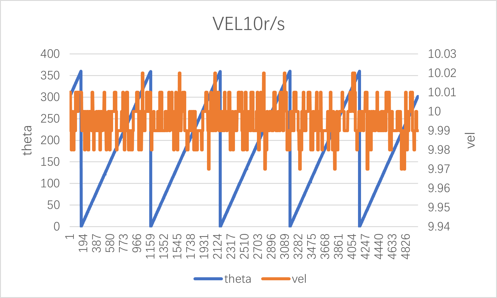
(1)vel10r/s
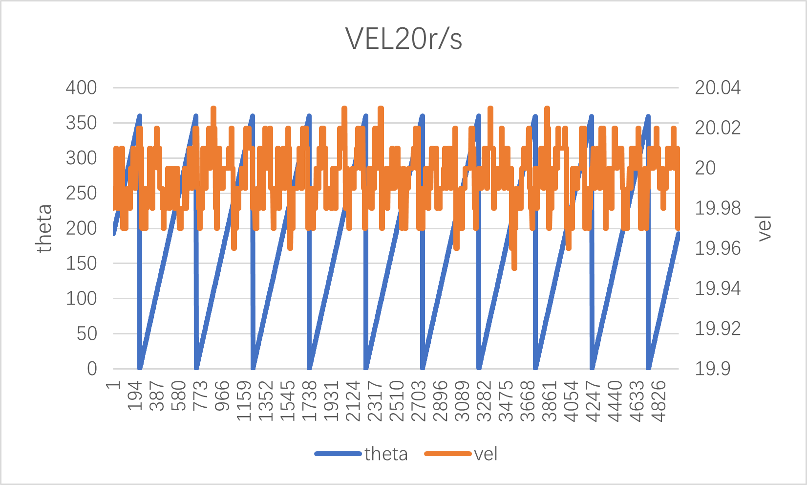
(2)vel20r/s
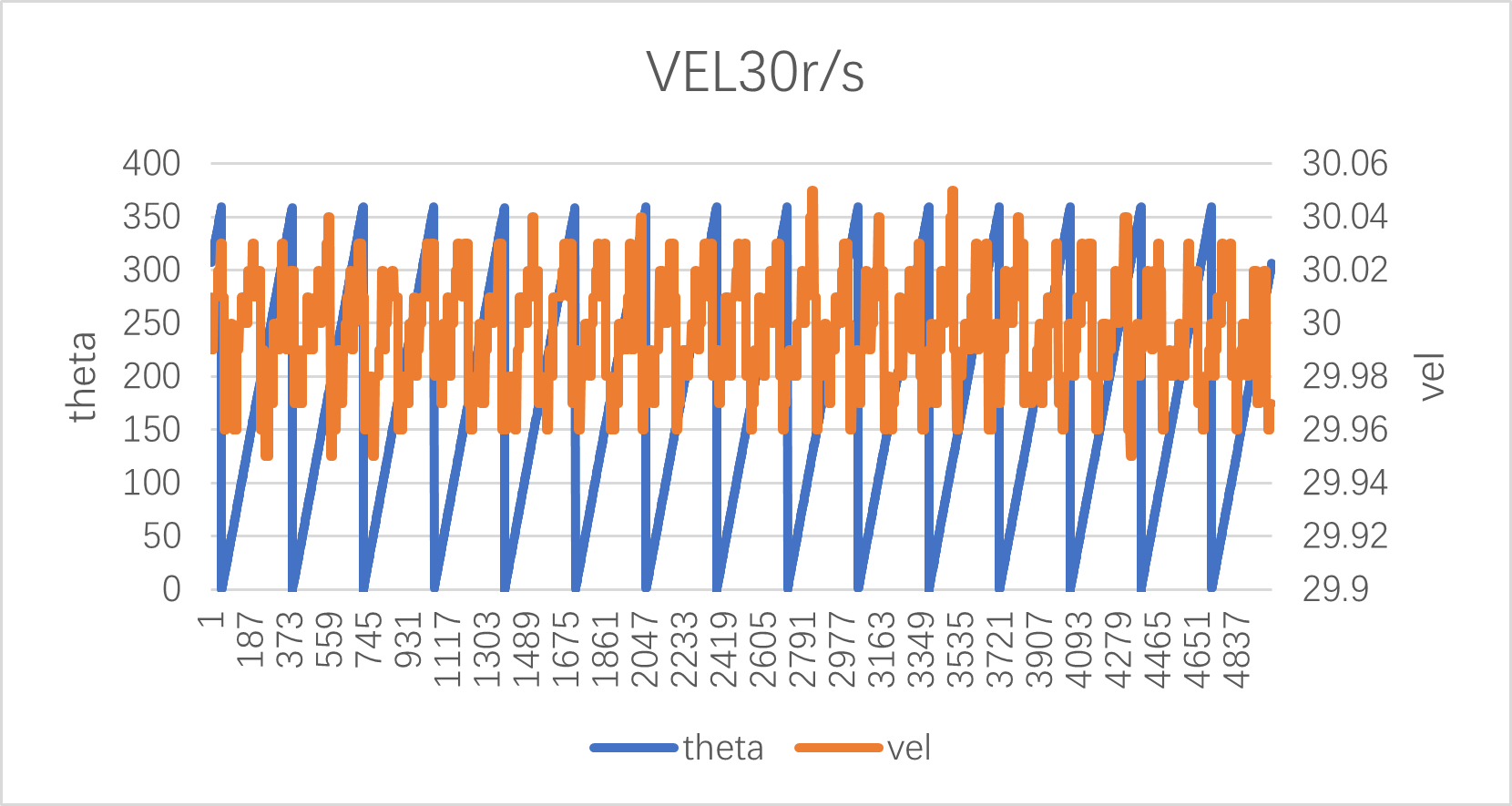
(3)vel30r/s
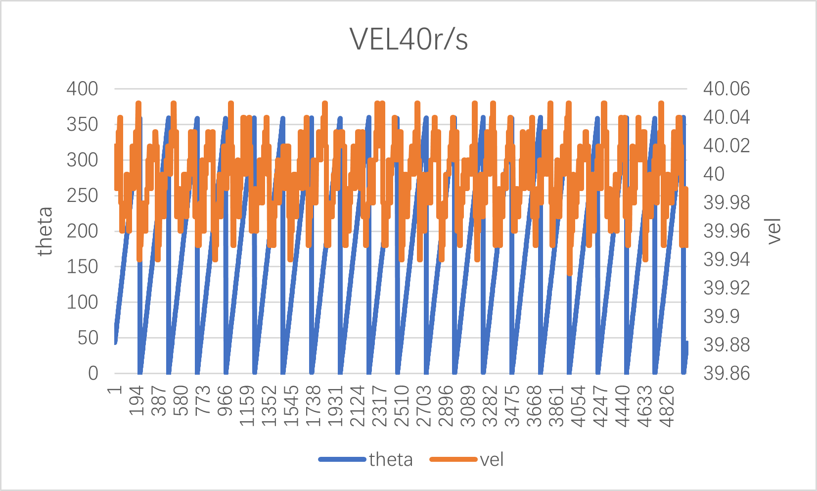
(4)vel40r/s
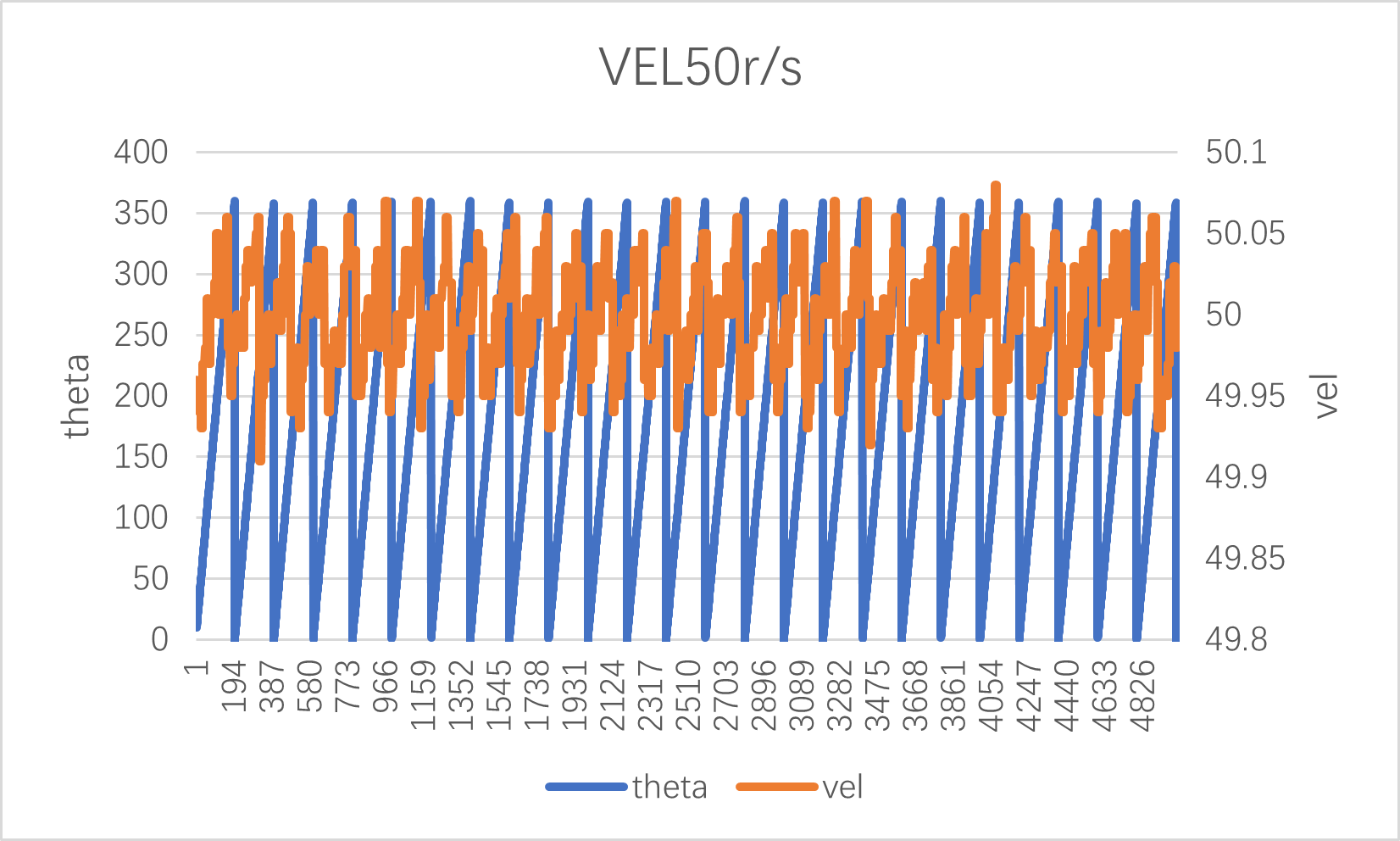
(5)vel50r/s
HPM APP is permissively licensed using the BSD 3-clause license