HPM APP
HPMicro Application solution
General software architecture solution for Power

Depend on SDK1.10.0

Introduction

  • The HPM Power solution summarizes the requirements of the power MCU, integrates them into a universal software solution, and provides various Application Programming Interface.
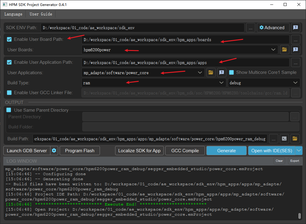
  • HPM Power Driver API is a power driver API interface based on the HPM Software Development Kit (HPM SDK).
  • The Power API abstracts a pair of PWM, PWM, and ADC channels on the hardware into custom ID numbers, allowing upper-layer applications to focus solely on the abstracted ID numbers.
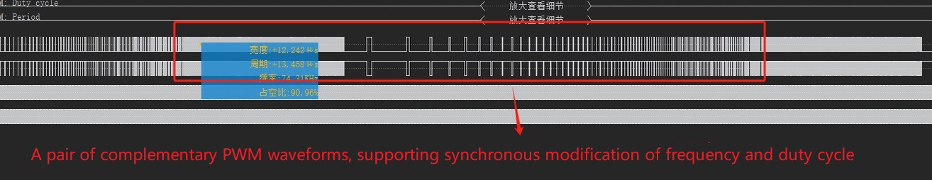
  • The Power API supports generating various paired PWM waveforms, such as complementary, center aligned waveforms, and edge aligned waveforms. It also includes features like deadzone insertion, fault protection, and forced outputs.
  • The Power API also supports a single PWM waveform, and a single PWM waveform also supports functions such as fault protection and forced output.
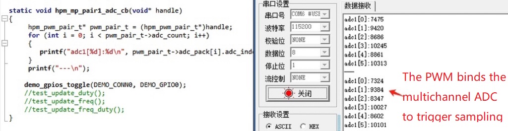
  • The Power API supports binding a pair of PWM or single PWM to a multi-channel ADC. It supports configuring the PWM to trigger ADC sampling at any duty cycle, and automatically trigger a callback function after the ADC sampling.
  • The Power API supports the configuration of a pair of PWM or single PWM to trigger a DMA request at any PWM duty cycle, allowing sequential ADC values (adjustable) to be sampled by DMA transport.
  • The Power API DMA supports chain mode and dual-buffer mode, enabling the automatic periodic sampling of ADC values (adjustable) in PING/PONG modes without CPU intervention. After each group of samples is acquired, it automatically triggers a callback funciton and initiates the sampling of the next group.
  • The Power API supports configuring PWM frequency, duty cycle, trigger time, etc.
  • The Power API supports the creation of high-precision timers (unit: microseconds).

Notes:

  • This solution does not include power loop algorithm content.
  • For the same PWM controller, modifying the PWM frequency of any channel will influence the frequency of all channels on the current controller.

general_solution

powerapi_main_en

Sample

A pair of PWM MAP table creation:

//power core ,warning: num1/num3 cmp all use 2
{
//CON0
{MP_PWM_PAIR_NUM_0, {{IOC_PAD_PB12, IOC_PB12_FUNC_CTL_PWM0_P_0}, {IOC_PAD_PB13, IOC_PB13_FUNC_CTL_PWM0_P_1}}, HPM_PWM0, 0, 0,
{{MP_PWM_TRIGGER_MODE_OUTPUT, 10, 10, HPM_TRGM0, HPM_TRGM0_INPUT_SRC_PWM0_CH10REF, TRGM_TRGOCFG_ADCX_PTRGI0A}}, {0}},
{MP_PWM_PAIR_NUM_1, {{IOC_PAD_PB14, IOC_PB14_FUNC_CTL_PWM0_P_2}, {IOC_PAD_PB15, IOC_PB15_FUNC_CTL_PWM0_P_3}}, HPM_PWM0, 2, 2,
{{MP_PWM_TRIGGER_MODE_OUTPUT, 11, 11, HPM_TRGM0, HPM_TRGM0_INPUT_SRC_PWM0_CH11REF, TRGM_TRGOCFG_ADCX_PTRGI0B}}, {0}},
{MP_PWM_PAIR_NUM_2, {{IOC_PAD_PB28, IOC_PB28_FUNC_CTL_PWM2_P_04}, {IOC_PAD_PB29, IOC_PB29_FUNC_CTL_PWM2_P_05}}, HPM_PWM2, 4, 4,
{{MP_PWM_TRIGGER_MODE_OUTPUT, 12, 12, HPM_TRGM2, HPM_TRGM2_INPUT_SRC_PWM2_CH12REF, TRGM_TRGOCFG_ADCX_PTRGI0A}}, {0}},
{MP_PWM_PAIR_NUM_3, {{IOC_PAD_PB30, IOC_PB30_FUNC_CTL_PWM2_P_06}, {IOC_PAD_PB31, IOC_PB31_FUNC_CTL_PWM2_P_07}}, HPM_PWM2, 6, 6,
{{MP_PWM_TRIGGER_MODE_OUTPUT, 13, 13, HPM_TRGM2, HPM_TRGM2_INPUT_SRC_PWM2_CH13REF, TRGM_TRGOCFG_ADCX_PTRGI0B}}, {0}},
//CON1
{MP_PWM_PAIR_NUM_4, {{IOC_PAD_PB00, IOC_PB00_FUNC_CTL_PWM1_P_0}, {IOC_PAD_PB01, IOC_PB01_FUNC_CTL_PWM1_P_1}}, HPM_PWM1, 0, 0,
{{MP_PWM_TRIGGER_MODE_OUTPUT, 10, 10, HPM_TRGM1, HPM_TRGM1_INPUT_SRC_PWM1_CH10REF, TRGM_TRGOCFG_ADCX_PTRGI0A}}, {0}},
{MP_PWM_PAIR_NUM_5, {{IOC_PAD_PB02, IOC_PB02_FUNC_CTL_PWM1_P_2}, {IOC_PAD_PB03, IOC_PB03_FUNC_CTL_PWM1_P_3}}, HPM_PWM1, 2, 2,
{{MP_PWM_TRIGGER_MODE_OUTPUT, 11, 11, HPM_TRGM1, HPM_TRGM1_INPUT_SRC_PWM1_CH11REF, TRGM_TRGOCFG_ADCX_PTRGI0B}}, {0}},
{MP_PWM_PAIR_NUM_6, {{IOC_PAD_PA24, IOC_PA24_FUNC_CTL_PWM3_P_04}, {IOC_PAD_PA25, IOC_PA25_FUNC_CTL_PWM3_P_05}}, HPM_PWM3, 4, 4,
{{MP_PWM_TRIGGER_MODE_OUTPUT, 12, 12, HPM_TRGM3, HPM_TRGM3_INPUT_SRC_PWM3_CH12REF, TRGM_TRGOCFG_ADCX_PTRGI0A}}, {0}},
{MP_PWM_PAIR_NUM_7, {{IOC_PAD_PA26, IOC_PA26_FUNC_CTL_PWM3_P_06}, {IOC_PAD_PA27, IOC_PA27_FUNC_CTL_PWM3_P_07}}, HPM_PWM3, 6, 6,
{{MP_PWM_TRIGGER_MODE_OUTPUT, 13, 13, HPM_TRGM3, HPM_TRGM3_INPUT_SRC_PWM3_CH13REF, TRGM_TRGOCFG_ADCX_PTRGI0B}}, {0}},
//CON2
{MP_PWM_PAIR_NUM_8, {{IOC_PAD_PB24, IOC_PB24_FUNC_CTL_PWM2_P_00}, {IOC_PAD_PB25, IOC_PB25_FUNC_CTL_PWM2_P_01}}, HPM_PWM2, 0, 0,
{{MP_PWM_TRIGGER_MODE_OUTPUT, 10, 10, HPM_TRGM2, HPM_TRGM2_INPUT_SRC_PWM2_CH10REF, TRGM_TRGOCFG_ADCX_PTRGI0A}}, {0}},
{MP_PWM_PAIR_NUM_9, {{IOC_PAD_PB26, IOC_PB26_FUNC_CTL_PWM2_P_02}, {IOC_PAD_PB27, IOC_PB27_FUNC_CTL_PWM2_P_03}}, HPM_PWM2, 2, 2,
{{MP_PWM_TRIGGER_MODE_OUTPUT, 11, 11, HPM_TRGM2, HPM_TRGM2_INPUT_SRC_PWM2_CH11REF, TRGM_TRGOCFG_ADCX_PTRGI0B}}, {0}},
{MP_PWM_PAIR_NUM_10, {{IOC_PAD_PB16, IOC_PB16_FUNC_CTL_PWM0_P_4}, {IOC_PAD_PB17, IOC_PB17_FUNC_CTL_PWM0_P_5}}, HPM_PWM0, 4, 4,
{{MP_PWM_TRIGGER_MODE_OUTPUT, 12, 12, HPM_TRGM0, HPM_TRGM0_INPUT_SRC_PWM0_CH12REF, TRGM_TRGOCFG_ADCX_PTRGI0A}}, {0}},
{MP_PWM_PAIR_NUM_11, {{IOC_PAD_PB18, IOC_PB18_FUNC_CTL_PWM0_P_6}, {IOC_PAD_PB19, IOC_PB19_FUNC_CTL_PWM0_P_7}}, HPM_PWM0, 6, 6,
{{MP_PWM_TRIGGER_MODE_OUTPUT, 13, 13, HPM_TRGM0, HPM_TRGM0_INPUT_SRC_PWM0_CH13REF, TRGM_TRGOCFG_ADCX_PTRGI0B}}, {0}},
//CON3
{MP_PWM_PAIR_NUM_12, {{IOC_PAD_PA20, IOC_PA20_FUNC_CTL_PWM3_P_00}, {IOC_PAD_PA21, IOC_PA21_FUNC_CTL_PWM3_P_01}}, HPM_PWM3, 0, 0,
{{MP_PWM_TRIGGER_MODE_OUTPUT, 10, 10, HPM_TRGM3, HPM_TRGM3_INPUT_SRC_PWM3_CH10REF, TRGM_TRGOCFG_ADCX_PTRGI0A}}, {0}},
{MP_PWM_PAIR_NUM_13, {{IOC_PAD_PA22, IOC_PA22_FUNC_CTL_PWM3_P_02}, {IOC_PAD_PA23, IOC_PA23_FUNC_CTL_PWM3_P_03}}, HPM_PWM3, 2, 2,
{{MP_PWM_TRIGGER_MODE_OUTPUT, 11, 11, HPM_TRGM3, HPM_TRGM3_INPUT_SRC_PWM3_CH11REF, TRGM_TRGOCFG_ADCX_PTRGI0B}}, {0}},
{MP_PWM_PAIR_NUM_14, {{IOC_PAD_PB04, IOC_PB04_FUNC_CTL_PWM1_P_4}, {IOC_PAD_PB05, IOC_PB05_FUNC_CTL_PWM1_P_5}}, HPM_PWM1, 4, 4,
{{MP_PWM_TRIGGER_MODE_OUTPUT, 12, 12, HPM_TRGM1, HPM_TRGM1_INPUT_SRC_PWM1_CH12REF, TRGM_TRGOCFG_ADCX_PTRGI0A}}, {0}},
{MP_PWM_PAIR_NUM_15, {{IOC_PAD_PB06, IOC_PB06_FUNC_CTL_PWM1_P_6}, {IOC_PAD_PB07, IOC_PB07_FUNC_CTL_PWM1_P_7}}, HPM_PWM1, 6, 6,
{{MP_PWM_TRIGGER_MODE_OUTPUT, 13, 13, HPM_TRGM1, HPM_TRGM1_INPUT_SRC_PWM1_CH13REF, TRGM_TRGOCFG_ADCX_PTRGI0B}}, {0}},
};
static const mp_pwm_pair_map_t pwm_pair_map[]
Definition: demo.c:21
@ MP_PWM_TRIGGER_MODE_OUTPUT
Output mode ;输出模式
Definition: mp_common.h:190
@ MP_PWM_PAIR_NUM_13
Definition: mp_common.h:74
@ MP_PWM_PAIR_NUM_2
Definition: mp_common.h:63
@ MP_PWM_PAIR_NUM_1
Definition: mp_common.h:62
@ MP_PWM_PAIR_NUM_3
Definition: mp_common.h:64
@ MP_PWM_PAIR_NUM_12
Definition: mp_common.h:73
@ MP_PWM_PAIR_NUM_6
Definition: mp_common.h:67
@ MP_PWM_PAIR_NUM_8
Definition: mp_common.h:69
@ MP_PWM_PAIR_NUM_5
Definition: mp_common.h:66
@ MP_PWM_PAIR_NUM_0
Definition: mp_common.h:61
@ MP_PWM_PAIR_NUM_9
Definition: mp_common.h:70
@ MP_PWM_PAIR_NUM_7
Definition: mp_common.h:68
@ MP_PWM_PAIR_NUM_14
Definition: mp_common.h:75
@ MP_PWM_PAIR_NUM_10
Definition: mp_common.h:71
@ MP_PWM_PAIR_NUM_15
Definition: mp_common.h:76
@ MP_PWM_PAIR_NUM_4
Definition: mp_common.h:65
@ MP_PWM_PAIR_NUM_11
Definition: mp_common.h:72
Address of a pair of PWM MAP data structure ;PWM 对MAP数据结构
Definition: mp_common.h:309

ADC MAP table creation:

static const mp_adc_map_t adc_map[] =
{
//CON0
{MP_ADC_NUM_0, IOC_PAD_PC04, HPM_ADC0, 0},
{MP_ADC_NUM_1, IOC_PAD_PC05, HPM_ADC0, 1},
{MP_ADC_NUM_2, IOC_PAD_PC08, HPM_ADC1, 0},
{MP_ADC_NUM_3, IOC_PAD_PC09, HPM_ADC1, 1},
{MP_ADC_NUM_4, IOC_PAD_PC12, HPM_ADC2, 0},
{MP_ADC_NUM_5, IOC_PAD_PC13, HPM_ADC2, 1},
//CON1
{MP_ADC_NUM_6, IOC_PAD_PC16, HPM_ADC0, 12},
{MP_ADC_NUM_7, IOC_PAD_PC17, HPM_ADC0, 13},
{MP_ADC_NUM_8, IOC_PAD_PC20, HPM_ADC1, 12},
{MP_ADC_NUM_9, IOC_PAD_PC21, HPM_ADC1, 13},
{MP_ADC_NUM_10, IOC_PAD_PC24, HPM_ADC2, 12},
{MP_ADC_NUM_11, IOC_PAD_PC25, HPM_ADC2, 13},
//CON2
{MP_ADC_NUM_12, IOC_PAD_PC06, HPM_ADC0, 2},
{MP_ADC_NUM_13, IOC_PAD_PC07, HPM_ADC0, 3},
{MP_ADC_NUM_14, IOC_PAD_PC10, HPM_ADC1, 2},
{MP_ADC_NUM_15, IOC_PAD_PC11, HPM_ADC1, 3},
{MP_ADC_NUM_16, IOC_PAD_PC14, HPM_ADC2, 2},
{MP_ADC_NUM_17, IOC_PAD_PC15, HPM_ADC2, 3},
//CON3
{MP_ADC_NUM_18, IOC_PAD_PC18, HPM_ADC0, 14},
{MP_ADC_NUM_19, IOC_PAD_PC19, HPM_ADC0, 15},
{MP_ADC_NUM_20, IOC_PAD_PC22, HPM_ADC1, 14},
{MP_ADC_NUM_21, IOC_PAD_PC23, HPM_ADC1, 15},
{MP_ADC_NUM_22, IOC_PAD_PC26, HPM_ADC2, 14},
{MP_ADC_NUM_23, IOC_PAD_PC27, HPM_ADC2, 15},
};
static const mp_adc_map_t adc_map[]
Definition: demo.c:61
@ MP_ADC_NUM_0
Definition: mp_common.h:109
@ MP_ADC_NUM_2
Definition: mp_common.h:111
@ MP_ADC_NUM_8
Definition: mp_common.h:117
@ MP_ADC_NUM_20
Definition: mp_common.h:129
@ MP_ADC_NUM_15
Definition: mp_common.h:124
@ MP_ADC_NUM_4
Definition: mp_common.h:113
@ MP_ADC_NUM_10
Definition: mp_common.h:119
@ MP_ADC_NUM_7
Definition: mp_common.h:116
@ MP_ADC_NUM_13
Definition: mp_common.h:122
@ MP_ADC_NUM_19
Definition: mp_common.h:128
@ MP_ADC_NUM_5
Definition: mp_common.h:114
@ MP_ADC_NUM_23
Definition: mp_common.h:132
@ MP_ADC_NUM_18
Definition: mp_common.h:127
@ MP_ADC_NUM_16
Definition: mp_common.h:125
@ MP_ADC_NUM_3
Definition: mp_common.h:112
@ MP_ADC_NUM_11
Definition: mp_common.h:120
@ MP_ADC_NUM_12
Definition: mp_common.h:121
@ MP_ADC_NUM_6
Definition: mp_common.h:115
@ MP_ADC_NUM_17
Definition: mp_common.h:126
@ MP_ADC_NUM_14
Definition: mp_common.h:123
@ MP_ADC_NUM_21
Definition: mp_common.h:130
@ MP_ADC_NUM_9
Definition: mp_common.h:118
@ MP_ADC_NUM_22
Definition: mp_common.h:131
@ MP_ADC_NUM_1
Definition: mp_common.h:110
ADC MAP data structure ;ADC MAP数据结构
Definition: mp_common.h:211

Define MP Power data objects :

#define MP_PAIR_COUNT 2
#define MP_PAIR_ADC_MAX 6
static hpm_adc_t hpm_adc[2][6]
Definition: demo.c:98
static hpm_pwm_pair_t hpm_pwm_pair[2]
Definition: demo.c:97
#define MP_PAIR_ADC_MAX
Definition: demo.c:94
static hpm_mp_t hpm_power
Definition: demo.c:96
#define MP_PAIR_COUNT
Definition: demo.c:93
ADC data structure ;ADC 数据结构
Definition: mp_common.h:386
Power MP data structure ;电源MP数据结构
Definition: mp_common.h:582
A pair of PWM data structure ;PWM 对数据结构
Definition: mp_common.h:452

Define MP and a pair of PWM trigger ADC sampling , execute callback function:

static void hpm_mp_pair1_adc_cb(void* handle)
{
hpm_pwm_pair_t* pwm_pair_t = (hpm_pwm_pair_t*)handle;
//Note: When enabling debug printing, it is essential to reduce the PWM frequency (lower interrupt frequency) to prevent anomalies.
for (int i = 0; i < pwm_pair_t->adc_count; i++)
{
printf("adc1[%d]:%d\n", pwm_pair_t->adc_pack[i].adc_index, pwm_pair_t->adc_pack[i].adc_data);
}
printf("---\n");
}
static void hpm_mp_pair1_adc_cb(void *handle)
Definition: demo.c:136
uint8_t adc_index
ADC index number(an abstract MAP sequence number) ;ADC 序号(MAP抽象序号)
Definition: mp_common.h:389
uint16_t adc_data
ADC data 16 bit ;ADC 采样值 16bit.
Definition: mp_common.h:404
uint8_t adc_count
The sum of the ADC sampled by the PWM triggered ADC ;PWM 触发ADC采样的ADC总和
Definition: mp_common.h:503
hpm_adc_t * adc_pack
ADC data structure hpm_adc_t ;ADC 数据结构 hpm_adc_t.
Definition: mp_common.h:509

Define MP High-resolution timer callback:

static void hpm_timer_cb(void)
{
printf("timer in!\n");
}
static void hpm_timer_cb(void)
Definition: demo.c:162

DEMO:

int main(void)
{
int ret;
board_init();
printf("hpm power initing...\n");
hpm_pwm_pair[0].adc_intr_index = MP_ADC_NUM_5; //The ID number of the ADC triggered interrupt
hpm_pwm_pair[0].adc_count = 6; // Bind 6 ADC to trigger sampling
hpm_pwm_pair[0].adc_pack = &hpm_adc[0][0]; //The binding ADC PACK pointer
hpm_pwm_pair[0].phase_angle = MP_PWM_PAIR_PHASE_ANGLE_0; //Phase degree adjustment is supported only in phase mode
hpm_pwm_pair[0].deadzone_start_halfcycle = 50; //The deadzone of the first halfcycle
hpm_pwm_pair[0].deadzone_end_halfcycle = 50; //The deadzone of the end halfcycle
hpm_pwm_pair[0].duty_count = hpm_pwm_pair[0].reload_count >> 1; //Initial duty cycle
hpm_pwm_pair[0].shadow_dutycount = 1; //Shadow dutycount
hpm_pwm_pair[0].trigger_count = 1; //Hardware trigger count
hpm_pwm_pair[0].trigger_enable = (1 << MP_PWM_TRIGGER_ADC_BIT); //PWM trigger ADC enable
hpm_pwm_pair[0].trigger_dutycount[MP_PWM_TRIGGER_ADC_BIT] = 1; //The time that PWM triggers ADC
//hpm_pwm_pair[1].pwm_pair_mode = MP_PWM_PAIR_MODE_CENTRAL; //central aligned
//hpm_pwm_pair[1].phase_angle = MP_PWM_PAIR_PHASE_ANGLE_90; //phase angle 90
hpm_power.pwm_pair_count = 2; //PWM pair count
hpm_power.pwm_sync_time_us = 0; //PWM pair Synchronization time
printf("hpm power init done, ret:%d\n", ret);
ret = hpm_mp_timer_create(1000*1000, hpm_timer_cb); //create timer
//Change the duty cycle
while (1)
{
}
return 0;
}
int main(void)
Definition: demo.c:199
static void hpm_keys_cb(uint8_t index, uint8_t level)
Definition: demo.c:167
void demo_gpios_init(uint8_t conn_index)
Definition: demo_gpio.c:151
@ DEMO_CONN0
Definition: demo_gpio.h:6
void demo_keys_init(demo_key_cb cb)
Definition: demo_key.c:72
void demo_leds_init(void)
Definition: demo_led.c:53
int hpm_mp_api_init(hpm_mp_t *mp_t)
Power API initialization ;电源API初始化
Definition: mp_api.c:90
void hpm_mp_api_pair_pwm_io_init(uint8_t pair_index)
A pair of PWM IO init ;PWM 对 IO初始化
Definition: mp_pwm.c:1504
void hpm_mp_api_adc_io_init(uint8_t adc_index)
ADC IO init ;ADC IO初始化
Definition: mp_adc.c:1473
int hpm_mp_api_pwmpair_duty(hpm_pwm_pair_t *pwm_pair_t, uint32_t duty)
A pair of PWM duty cycle Settings Note: The duty cycle ranges from 0 to reload_count(reload_count is ...
Definition: mp_pwm.c:1354
int hpm_mp_api_adc_set_map(const mp_adc_map_t *map_t, int count)
Settings for the ADC MAP ;ADC MAP设置
Definition: mp_adc.c:1479
int hpm_mp_api_pwm_pair_set_map(const mp_pwm_pair_map_t *map_t, int count)
Settings for a pair of PWM MAP ;PWM对 MAP设置
Definition: mp_pwm.c:1522
int hpm_mp_pwm_pair_get_default(uint8_t pwm_pair_index, uint32_t freq, hpm_pwm_pair_t *pwm_pair_t)
Get the default value of a pair of PWM (two PWM channels as a pair) data structure ;获取PWM对(两路PWM成一对...
Definition: mp_api.c:22
#define MP_PWM_TRIGGER_ADC_BIT
PWM trigger for ADC bit ;PWM互联触发ADC采样BIT位
Definition: mp_common.h:204
int hpm_mp_api_get_default(hpm_mp_t *mp_t)
Get the default value of the power data structure ;电源数据结构默认值获取
Definition: mp_api.c:12
int hpm_mp_timer_create(uint32_t us, mp_timer_cb cb)
High precision timer creation ;高精定时器创建
Definition: mp_timer.c:23
int hpm_mp_adc_get_default(uint8_t adc_index, hpm_adc_t *adc_t)
Get the default value of the ADC data structure ;获取ADC数据结构默认值
Definition: mp_api.c:82
@ MP_PWM_PAIR_MODE_REVERSE
complementary mode ;互补模式
Definition: mp_common.h:143
@ MP_PWM_PAIR_PHASE_ANGLE_0
0 angle ;0度
Definition: mp_common.h:158
uint8_t pwm_pair_count
The sum total of the pair of PWM ;PWM对 总和
Definition: mp_common.h:585
uint32_t pwm_sync_time_us
Synchronization time of a pair of PWM; ==0- Fully synchronized; >0- phase difference time; ;PWM对 同步时间...
Definition: mp_common.h:588
hpm_pwm_pair_t * pwm_pair
A pair of PWM data structure Pointers ;PWM对 数据结构指针
Definition: mp_common.h:591
uint32_t trigger_dutycount[(8)]
PWM duty cycle at the moment when the ADC triggered, (0..reload_count) ;PWM 互联触发ADC时刻占空比,...
Definition: mp_common.h:500
uint8_t trigger_count
The sum total of a pair of PWM TRGM ;PWM 对互联触发总和
Definition: mp_common.h:494
uint8_t pwm_pair_mode
A pair of PWM mode mp_pwm_pair_mode ;PWM 对模式 mp_pwm_pair_mode.
Definition: mp_common.h:461
uint8_t phase_angle
A pair of PWM phase angles(used in phase center aligned mode and edge aligned mode) mp_pwm_pair_phase...
Definition: mp_common.h:464
uint8_t trigger_enable
Enable a pair of PWM TRGM(Each bit represents once trigger enable) ;PWM 对互联触发使能(每个bit代表一个触发使能)
Definition: mp_common.h:497
uint32_t reload_count
A pair of PWM reload_count, obtained by 'get default', cannot be changed ;PWM 对reload_count,...
Definition: mp_common.h:479
uint32_t deadzone_start_halfcycle
Starting time for a pair of PWM dead zone insertions. The unit is half of the PWM bus frequency ;PWM ...
Definition: mp_common.h:467
uint32_t deadzone_end_halfcycle
Ending time for a pair of PWM dead zone insertions. The unit is half of the PWM bus frequency ;PWM 对死...
Definition: mp_common.h:470
uint8_t adc_intr_index
The ADC channel number that enables ADC interrupts after the completion of ADC sampling (regardless o...
Definition: mp_common.h:506
hpm_mp_adc_over_callback adc_over_callback
ADC callback after the end of sampling ;ADC采样结束后回调
Definition: mp_common.h:512
uint32_t shadow_dutycount
PWM duty cycle at the moment when the shadow register takes effect, (0..reload_count) ;PWM 影子寄存器生效时刻占...
Definition: mp_common.h:485
uint32_t duty_count
A pair of PWM duty count, (0..reload_count) ;PWM 对占空比, (0..reload_count)
Definition: mp_common.h:482

Code Path

  • Code Path:mp_adapte/software/power_core

Code Configuration

none

Code Build

  • Build for windows WIN
  • Build for linux
    //Switch to the sample application directory
    cd hpm_apps\apps\mp_adapte\software\power_core
    //create build directory
    mkdir build
    //Switch directory to "build"
    cd build
    //Ninja-build
    cmake -GNinja -DBOARD_SEARCH_PATH=/home/work/workspace/hpm_apps/boards -DBOARD=hpm6200power -DCMAKE_BUILD_TYPE=flash_xip ..
    //Build
    ninja

Hardware

  • The HPM6200power board used in this solution.
  • Users can use the EVK board , but users need to pay attention to modifying the corresponding pin.

Code Run

  • Code Run
  • Using a logic analyzer or an oscilloscope,Connect pins to view multichannel PWM, deadzone time, or PWM waveform.
  • Analog input ADC captures voltage,and by increasing the printf, observe the sampled ADC values.
  • Simulate external fault input and use a logic analyzer or oscilloscope to check if the fault protection responds.

The following is the waveform diagram:

  • A pair of complementary PWM waveforms /a pair of PWM waveforms with center-aligned phases. result_pwm_pair
  • A pair of PWM complementary waveforms, simultaneously adjusting frequency and duty cycle. result_pwm_pair_freq_duty_update
  • A pair of PWM can trigger multiple ADC sampling result_pwm_adc

Licensing

HPM APP is permissively licensed using the BSD 3-clause license